Micro-channel electrolytic machining device

A processing device and micro-channel technology, applied in electrochemical processing equipment, metal processing equipment, manufacturing tools, etc., can solve the problems of immature micro-channel technology, poor product accuracy, high equipment cost, etc., to prevent quality reduction, The effect of reducing the number of processing times and improving processing efficiency

Active Publication Date: 2018-10-12
GUANGDONG UNIV OF TECH
View PDF6 Cites 2 Cited by
  • Summary
  • Abstract
  • Description
  • Claims
  • Application Information

AI Technical Summary

Problems solved by technology

[0008] In view of this, the object of the present invention is to provide a micro-channel electrolytic machining device, the structural design of which can effectively solve the problem that the current micro-channel processing technology using electrolysis is immature, which is likely to cause high equipment costs. , low efficiency or poor product accuracy, low pass rate and other technical problems

Method used


Image

  • Micro-channel electrolytic machining device
  • Micro-channel electrolytic machining device
  • Micro-channel electrolytic machining device

Examples


Embodiment Construction

[0026] The embodiment of the present invention discloses a micro-channel electrolytic processing device to solve the technical problems that the current micro-channel processing technology using electrolysis is immature, which may easily cause high equipment cost, low efficiency, poor product accuracy, and low pass rate. .

[0027] The following will clearly and completely describe the technical solutions in the embodiments of the present invention with reference to the accompanying drawings in the embodiments of the present invention. Obviously, the described embodiments are only some, not all, embodiments of the present invention. Based on the embodiments of the present invention, all other embodiments obtained by persons of ordinary skill in the art without making creative efforts belong to the protection scope of the present invention.

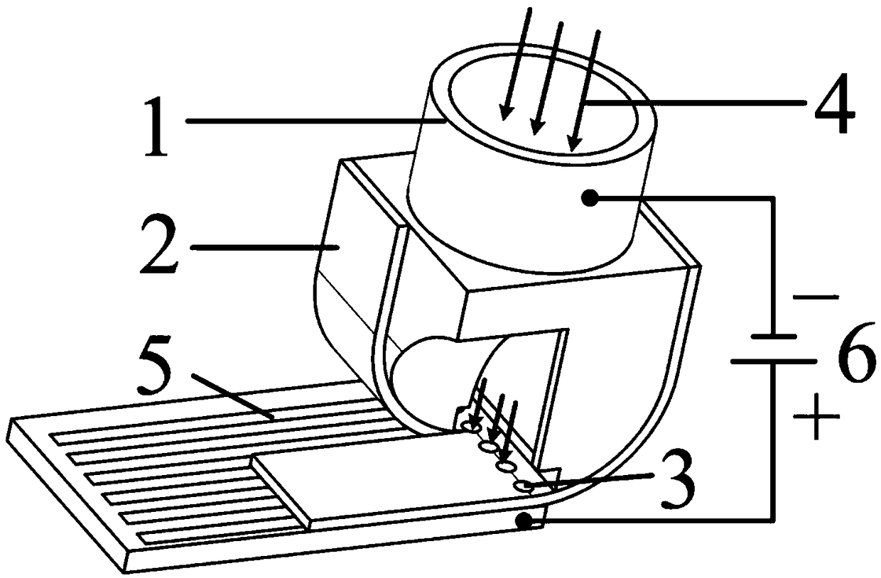
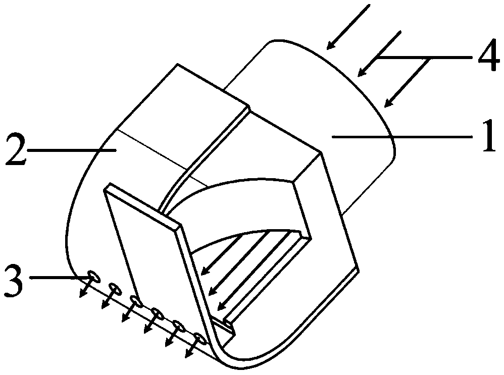
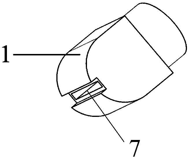
[0028] see Figure 1-Figure 3 , figure 1 Schematic diagram of the working principle of the microchannel electrolytic machining device p...


PUM

PropertyMeasurementUnit
Radius rangeaaaaaaaaaa
Apertureaaaaaaaaaa

Abstract

The invention discloses a micro-channel electrolytic machining device. The micro-channel electrolytic machining device comprises a spray nozzle used for spraying out an electrolyte. A slit-shaped nozzle is arranged at the spray-out end of the spray nozzle. The spray nozzle is connected with an insulation template used for shielding the electrolyte. A micro-through hole set is formed in the position, corresponding to the slit-shaped nozzle, of the insulation template. The hole diameters of micro holes in the micro-through hole set are matched with widths of to-be-machined micro channels. The design of the spray nozzle is improved, the slit-shaped nozzle is arranged, the fed electrolyte is evenly distributed in a slit range, the insulation template provided with the micro-through hole set isconnected with the spray nozzle, output of the electrolyte to the surface of a workpiece is achieved through the micro through holes in the insulation template, due to the sealing performance of theinsulation template, the electrolyte can be effectively prevented from diffusing to non-machining areas of the workpiece, and the surface quality of the workpiece is prevented from being lowered; andthe widths of the machined micro channels are determined by the micro through holes, thus, the micro channels in different sizes can be machined by adopting insulation templates with different hole diameters, the equipment utilization rate is increased, and the cost is reduced.

Description

technical field [0001] The invention relates to the technical field of electrolytic machining, and more specifically relates to a microchannel electrolytic machining device. Background technique [0002] The microchannel structure is a typical precision component structure. The width and depth of the structure are tens to hundreds of microns. It is usually made of difficult-to-machine titanium alloy or stainless steel. Its manufacture is a typical Micro / Meso processing task. Components with micro-channel structure have been widely used in high-tech products in the fields of energy, power electronics, chemical industry and aerospace, and are the core components that determine product performance and quality. [0003] In recent years, a variety of manufacturing and processing methods have been proposed for the manufacturing and processing of metal microfluidic channel structures. At present, the processing methods mainly include laser processing technology, abrasive gas jet te...

Claims


Application Information

Patent Timeline
IPC IPC(8): B23H3/00B23H9/16
CPCB23H3/00B23H9/16
Inventor 陈晓磊董邦彦张传运郭钟宁张永俊罗红平
Owner GUANGDONG UNIV OF TECH
Why Eureka
Try Eureka