Triple-effect photovoltaic photo-thermal wall combined with building

A combined and wall-mounted technology, applied in the field of photovoltaic-thermal building integration, can solve problems such as poor economy, low reliability, and overheating in summer, and achieve the effects of reducing heat load, cooling load, and avoiding indoor overheating

Pending Publication Date: 2018-10-12
UNIV OF SCI & TECH OF CHINA
View PDF6 Cites 6 Cited by
  • Summary
  • Abstract
  • Description
  • Claims
  • Application Information

AI Technical Summary

Problems solved by technology

In photovoltaic / photothermal building integrated equipment, the active heating mode is less economical and less reliable, while passive heating can easily lead to problems such as overheating in summer

Method used


Image

  • Triple-effect photovoltaic photo-thermal wall combined with building
  • Triple-effect photovoltaic photo-thermal wall combined with building
  • Triple-effect photovoltaic photo-thermal wall combined with building

Examples


Embodiment 1

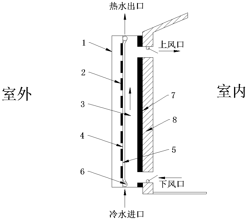
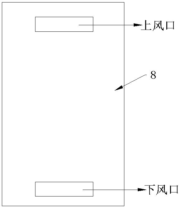
[0033] see figure 1 , a three-effect photovoltaic photothermal wall combined with a building includes a wall 8 located on the sunny side of the building, see image 3 , the upper part of the wall 8 is provided with an upper vent 9, and the lower part is provided with a lower vent 10. The upper vent 9 and the lower vent 10 are rectangular openings with the same structure, and the opening width of each vent is 1 / 2 of the width of the collector. 70%, the opening height of each vent is 150mm. It also includes photovoltaic photothermal components, and the photovoltaic photothermal components are arranged on the outer side of the wall 8 .

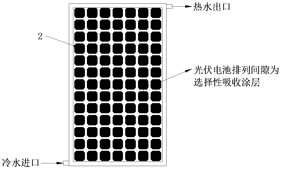
[0034] The photovoltaic photothermal module includes transparent cover plates 1 and heat collectors parallel to each other. The heat collector is a rectangular box structure, and the height of the heat collector is not less than 2m to ensure a large thermosiphon force.

[0035] The heat collector includes evenly arranged photovoltaic panels 2 ,...

Embodiment 2

[0043] The structure of this embodiment is the same as that of Embodiment 1, except that the thickness of the air channel 3 is 150 mm, and the air inside the air channel 3 can flow at a speed greater than 0.04 m / s; the thickness of the air interlayer is 20 mm.

[0044] In this example, when the heating room is made of red brick walls with a thickness of 240mm, the room is 3.00m (width)*3.00m (depth)*2.66m (height), the daytime radiation is good in winter and the average outdoor temperature is -3°C, the set The daylighting area of ​​the heater accounts for 95% of the total area of ​​the south wall. This system can realize the indoor temperature rise to 22°C, and the average power generation throughout the day is 250W. In summer, when the radiation is good and the average outdoor temperature is 25°C, the total capacity of the water tank is 350L. The system can realize the temperature of the water tank to rise to 60°C, and the average power generation throughout the day is 200W.


PUM


Abstract

The invention relates to a triple-effect photovoltaic photo-thermal wall combined with a building. An upper ventilation opening and a lower ventilation opening are separately formed in a wall of one side face, toward the sun, of the building; a photovoltaic photo-thermal assembly is arranged on the outer side face of the wall; the photovoltaic photo-thermal assembly comprises a transparent cover plate and a heat collector parallel to each other; an air runner is formed between one side face of a drain pipe of the heat collector and the wall, and the upper and lower ends of the air runner separately communicate to the upper and lower ventilating openings; a sealed air interlayer is formed between one side face of a photovoltaic battery panel of the heat collector and the transparent cover plate; when the system works in winter, a hot water heat collecting system stops operating; both the upper ventilating opening and the lower ventilating opening in the wall are opened to heat indoor air through natural circulation, so that the indoor temperature is raised by 5-10 DEG C. When the system works in spring, summer and autumn, the hot water heat collecting system operates; both the upperventilating opening and the lower ventilating opening in the wall are closed, an indoor heating system stops operating, and the instant heat efficiency of the heat collector reaches 40-45%.

Description

technical field [0001] The invention belongs to the technical field of photovoltaic photothermal building integration, and in particular relates to a photovoltaic photothermal wall combined with a building. Background technique [0002] With the continuous improvement of people's living standards, the requirements for living comfort are getting higher and higher, and the demand for building energy consumption will continue to grow. At the same time, the proportion of clean building energy in building energy supply is also increasing year by year. Solar energy is widely distributed but the energy flux density is low, which requires a large receiving area, and the roof and south wall of the building have a large area that can be used. Combining solar energy with buildings can meet a variety of energy needs in buildings, and vigorously promoting the application of solar photovoltaic photothermal building integrated technology in buildings will be an important way to develop ren...

Claims


Application Information

Patent Timeline
Patent Type & Authority Applications(China)
IPC IPC(8): F24S20/66H02S40/44F24D15/00
CPCH02S40/44F24D15/00F24D2200/14Y02E10/60Y02B10/10Y02E10/50Y02B10/20Y02B10/70
Inventor 季杰周帆
Owner UNIV OF SCI & TECH OF CHINA
Why Eureka
Try Eureka