Cold exchange system and method for comprehensively utilizing cold energy of liquefied natural gas

A technology of liquefied natural gas and cold system, which is applied in the pipeline system, energy industry, indirect heat exchanger, etc., can solve the problems of cold pollution in the surrounding environment, waste of LNG cold energy, etc., to reduce the environmental hazards of low temperature, reduce carbon emissions, The effect of operating costs on production

Pending Publication Date: 2018-10-12
中海油能源发展股份有限公司清洁能源分公司 +1
View PDF0 Cites 7 Cited by
  • Summary
  • Abstract
  • Description
  • Claims
  • Application Information

AI Technical Summary

Problems solved by technology

LNG will release a large amount of cold energy during the vaporization process. Traditional large and medium-sized LNG receiving stations use open-frame seawater vaporizers, submerged c

Method used


Image

  • Cold exchange system and method for comprehensively utilizing cold energy of liquefied natural gas
  • Cold exchange system and method for comprehensively utilizing cold energy of liquefied natural gas

Examples


Embodiment 1

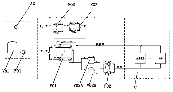
[0021] Such as figure 1 As shown, a cooling station system and device that comprehensively utilizes the cold energy of liquefied natural gas. The refrigerant absorbs the cooling capacity of LNG; the brine that has been cooled after heat exchange passes through the brine buffer tank and is boosted by the brine pump P02, and the pressurized brine enters the downstream and uses the cooling user A1 to provide cooling capacity for it; The brine that has been reheated by the cooling user A1 returns to the brine heat exchanger E01 and is recycled after being cooled; the natural gas that has exchanged heat with the brine enters the first natural gas thermostat E02 and the second natural gas temperature regulator in series. The thermostat E03 is reheated and sent to the natural gas pipeline network A2. When the supply of LNG cold energy is temporarily interrupted, the brine buffer tank can continue to supply brine for a period of time, so as to satisfy the downstream cold user A1 to s...

Embodiment 2

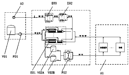
[0029] Such as figure 2 The difference from Example 1 is that the heat exchange process between the brine and LNG is a secondary heat exchange, and the secondary heat exchange means that the LNG first exchanges heat with the intermediate refrigerant, and then the intermediate refrigerant exchanges heat with the brine. hot. LNG first exchanges heat with the intermediate refrigerant in the refrigerant heat exchanger, and transfers the cold energy of LNG to the intermediate refrigerant; then the intermediate refrigerant exchanges heat with the refrigerant, and transfers the cold energy to the refrigerant. In this process, the LNG cold energy is transferred to the brine through two heat exchanges. The brine heat exchanger in the secondary heat exchange system is a three-channel shell-and-tube heat exchanger, in which the liquefied natural gas goes through the tube side, The intermediate refrigerant goes through the shell side, and the secondary refrigerant goes through the other...


PUM


Abstract

The invention discloses a cold exchange system and method for comprehensively utilizing cold energy of liquefied natural gas. LNG is collected through an LNG storage tank and then pressurized by an LNG pump, the LNG enters refrigerating medium heat exchangers for heat exchange, and a refrigerating medium absorbs the cold energy of LNG and is pressurized by the refrigerating medium pump for use bycold users; after being used by the cold users, the reheated refrigerating medium returns to the refrigerating medium heat exchangers for recycling, and the LNG with cold energy absorbed by the refrigerating medium enters a natural gas pipeline network after being subjected to thermoregulation by natural gas thermostats, the cold energy in the LNG vaporization process is fully used, the LNG cold energy can be used in the ice and snow world, cold storages of different scales, ice making, circulating water stations, air conditioners and other types of cold users, the cold pollution caused by thesurrounding environment during LNG gasification can be effectively reduced, meanwhile the cooling power consumption of downstream cold users is saved, the carbon emission is reduced, and the production and operation costs of the downstream cold users are lowered.

Description

technical field [0001] The invention relates to the technical field of cold exchange, in particular to a cold exchange system and method for comprehensively utilizing the cold energy of liquefied natural gas. Background technique [0002] Liquefied natural gas (LNG) is currently one of the cleanest energy sources that can be used industrially in the world. As a green and efficient energy source, it is becoming more and more popular. Many fields have listed LNG as the preferred fuel. The proportion of natural gas in energy supply is rapidly increasing. LNG will release a large amount of cold energy during the vaporization process. Traditional large and medium-sized LNG receiving stations use open-frame seawater vaporizers, submerged combustion vaporizers, etc. to reheat LNG and send it to the pipeline network, which not only wastes valuable LNG cold energy, Also produce cold pollution to surrounding environment. Therefore, it is necessary to make full and effective use of L...

Claims


Application Information

Patent Timeline
IPC IPC(8): F28D7/00F17D3/01
CPCF17D3/01F28D7/00Y02P80/10
Inventor 吕志榕江蓉张磊向润清魏林瑞赖勇杰王大伟
Owner 中海油能源发展股份有限公司清洁能源分公司
Why Eureka
Try Eureka