
Device and method for microleak identification of coal-powder boiler or circulating fluidized bedboiler

A technology of circulating fluidized bed and pulverized coal furnace, which is applied in the device field of automatic identification and alarming, and the device field of identifying the alarm when micro leakage occurs in pulverized coal furnace or circulating fluidized bed boiler. It is easy to analyze historical data, save time and cost, and reduce economic losses.

Inactive Publication Date: 2018-10-12
高振宇 +3
View PDF6 Cites 9 Cited by
  • Summary
  • Abstract
  • Description
  • Claims
  • Application Information

AI Technical Summary

Problems solved by technology

[0002] Domestic power plant boilers have four-tube leakage to varying degrees, which seriously affects the safe and stable operation of power generation enterprises
If the leakage of the boiler cannot be detected and dealt with in time, it will not only seriously affect the economic benefits of the power plant (long shutdown time will lead to increased power loss and increased maintenance costs), but also increase the difficulty of maintenance
[0003] The existing domestic methods for judging boiler leakage are: ultrasonic testing or indirect determination through the difference between boiler main feed water and main steam, which is easily disturbed by noise, boiler blowdown, soot blowing and other factors, and the leakage in the low pressure section is not obvious

Method used


Image

  • Device and method for microleak identification of coal-powder boiler or circulating fluidized bedboiler
  • Device and method for microleak identification of coal-powder boiler or circulating fluidized bedboiler
  • Device and method for microleak identification of coal-powder boiler or circulating fluidized bedboiler

Examples


Embodiment Construction

[0019] In order to facilitate those of ordinary skill in the art to understand and implement the present invention, the present invention will be described in further detail below in conjunction with the accompanying drawings and embodiments. It should be understood that the implementation examples described here are only used to illustrate and explain the present invention, and are not intended to limit this invention.

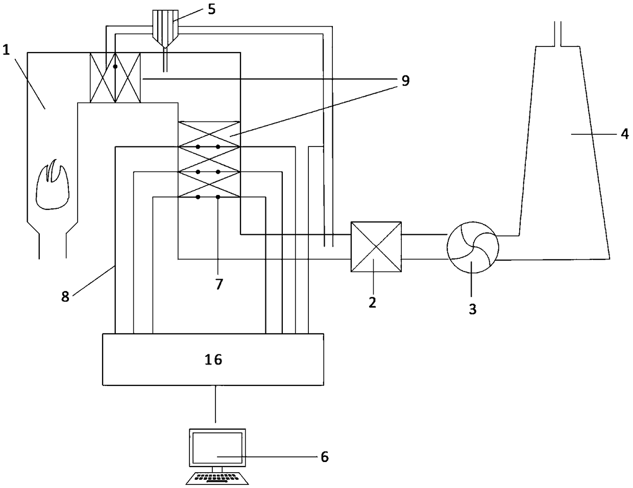
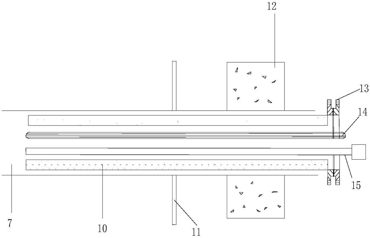
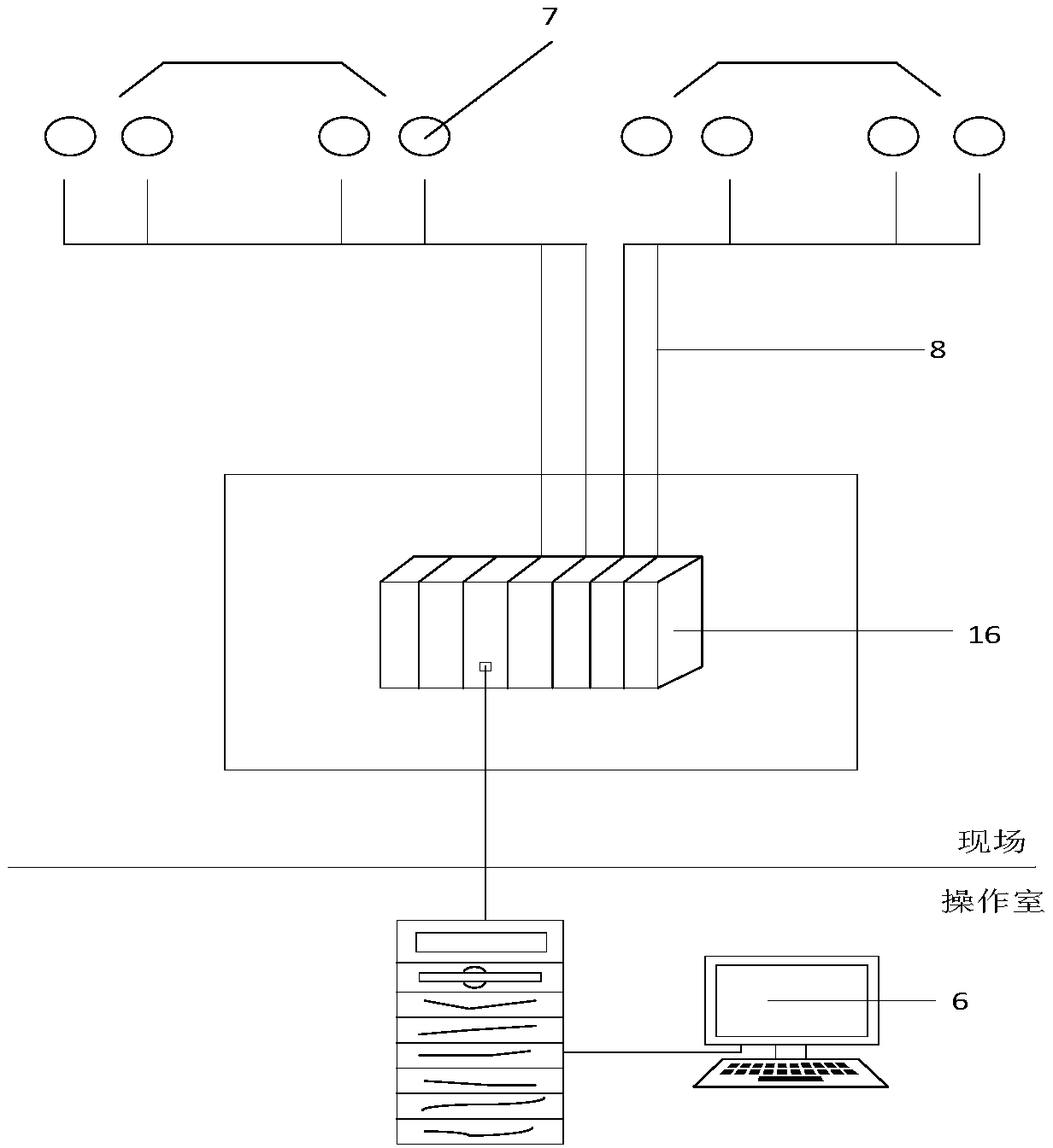
[0020] please see figure 1 , 2 and image 3 , a device for identifying micro-leakage of a pulverized coal furnace or a circulating fluidized bed boiler provided by the present invention includes a furnace flue 1, a dust collector 2, an induced draft fan 3, a chimney 4, a dust-proof device 5, a computer 6, and a Hole measuring point 7, cable 8, heating surface 9, thermocouple 14, hygrometer 15, PLC system 16. Select measuring points on both sides of the heating surface 9 in the furnace flue 1 and open holes. The opening measuring points 7 are distributed on...


PUM


Abstract

The present invention discloses a device and a method for microleak identification of a coal-powder boiler or a circulating fluidized bedboiler. The device comprises a hearth flue, a dust remover, aninduced draft fan, a chimney, a computer, trepanning measurement points, a thermocouple, a hygrometer and a PLC system. The two sides of the heating surface in the hearth flue are provided with the plurality of trepanning measurement points, the trepanning measurement points are internally provided with protective casings; the thermocouple and the hygrometer are respectively arranged in the protective casings to measure the temperatures and the humidities of different heating surfaces in real time and transmit the measurement values into the PLC system through cables; the PLC system is connected with the computer, the PLC system is configured for data analysis and processing, an analysis result can be displayed on the computer in a curve mode, if the humidity curve trend of a certain pointor the humidity difference of some two points reaches a threshold value, leakage alarm is emitted, and the positions of the heating surfaces are confirmed to perform furnace shutdown maintenance. Thedevice and the method for microleak identification of a coal-powder boiler or a circulating fluidized bedboiler can discover problems and can emit alarm when the leakage amount is little, and can discover the preliminary position of the leak surface.

Description

technical field [0001] The invention belongs to the technical field of safety and detection equipment, and relates to a device for identifying micro-leakage of a pulverized coal furnace or a circulating fluidized bed boiler, and in particular to a micro-leakage of a pulverized coal furnace or a circulating fluidized bed boiler (not greater than 5t / h), it is a device that automatically recognizes and sends out an alarm, and is suitable for all boilers that use coal as fuel. technical background [0002] Domestic power plant boilers have four-tube leakage to varying degrees, which seriously affects the safe and stable operation of power generation enterprises. If the leakage of the boiler cannot be found and dealt with in time, it will not only seriously affect the economic benefits of the power plant (long shutdown time will lead to increased power loss and increased maintenance costs), but also increase the difficulty of maintenance. [0003] The existing domestic methods f...

Claims


Application Information

Patent Timeline
Patent Type & Authority Applications(China)
IPC IPC(8): G01M3/02
CPCG01M3/02
Inventor 高振宇何剑高梓超王先培杨同忠刘宇飞
Owner 高振宇
Learn More