Switched reluctance motor with water-injected winding and multi-directional self-circulating ventilation system

A switched reluctance motor, self-circulation technology, applied in the direction of cooling/ventilation devices, electric components, electromechanical devices, etc., can solve the temperature increase of the stator core and stator copper windings, which threatens the safe and stable operation of large-capacity switched reluctance motors, and limits Increase the capacity of switched reluctance motors to achieve the effect of improving cooling capacity and density power, reducing temperature and saving materials

Active Publication Date: 2020-03-03
HARBIN UNIV OF SCI & TECH
View PDF4 Cites 1 Cited by
  • Summary
  • Abstract
  • Description
  • Claims
  • Application Information

AI Technical Summary

Problems solved by technology

However, as the capacity of switched reluctance motors continues to increase, the temperature rise of the stator core and stator copper windings of switched reluctance motors increases significantly. The temperature of stator core and stator copper winding increases sharply, even exceeding the allowable temperature rise of insulation, which seriously threatens the safe and stable operation of large-capacity switched reluctance motors. At the same time, it limits the development of large-capacity switched reluctance motors.

Method used


Image

  • Switched reluctance motor with water-injected winding and multi-directional self-circulating ventilation system
  • Switched reluctance motor with water-injected winding and multi-directional self-circulating ventilation system
  • Switched reluctance motor with water-injected winding and multi-directional self-circulating ventilation system

Examples


specific Embodiment approach 1

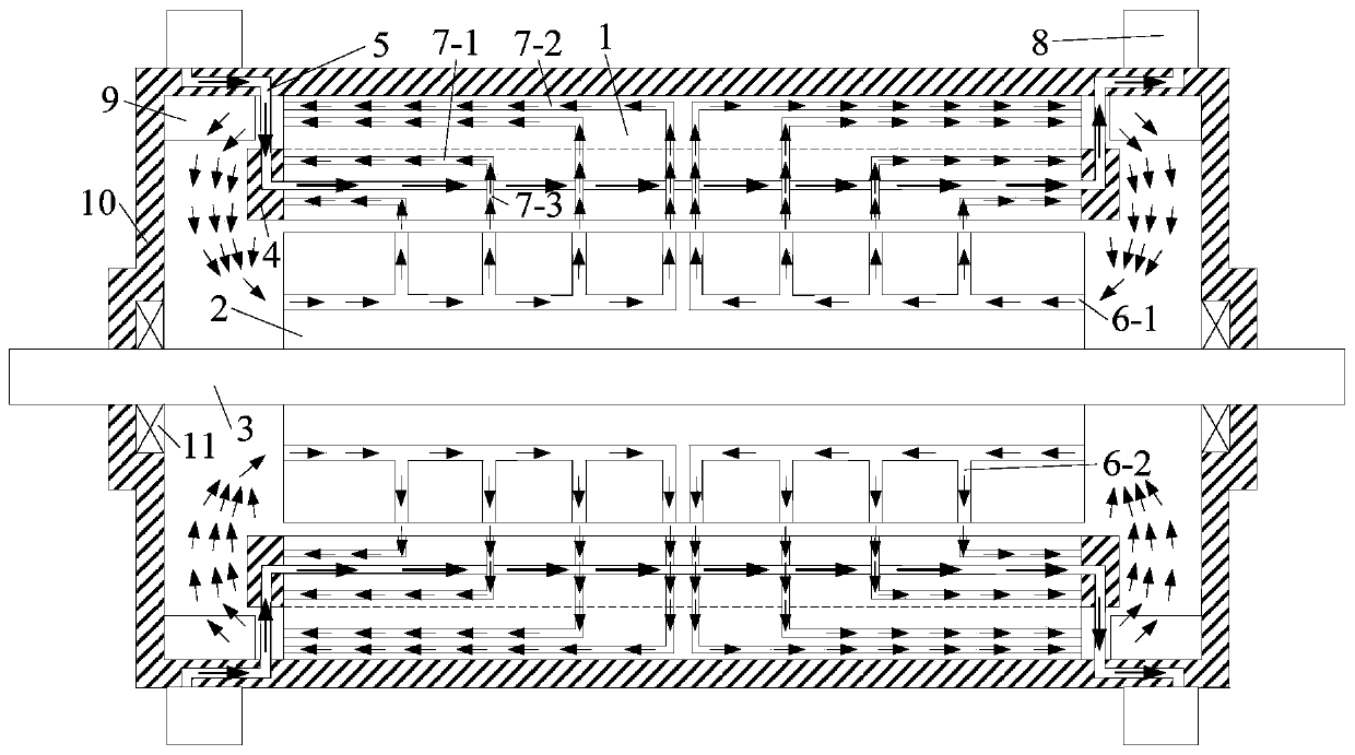
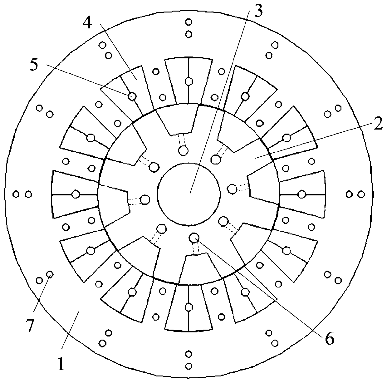
[0024] Specific implementation mode one, such as figure 1 and figure 2 As shown, the arrows in the figure show the flow direction of the cooling gas in the switched reluctance motor with water injection winding and multi-directional self-circulating ventilation system. The switched reluctance motor with water injection winding and multi-directional self-circulating ventilation system according to the present invention includes stator core 1, rotor core 2, rotor shaft 3, stator copper winding 4, stator direct cooling water pipe 5, and rotor direct cooling ventilation channel 6. Stator direct cooling air passage 7, stator direct cooling water drive device 8, sheet heat conduction plate 9, machine base 10 and bearing 11;

[0025] The rotor shaft 3 is installed on the base 10 through the bearing 11, the rotor core 2 is installed on the rotor shaft 3, the stator core 1 is installed on the inner wall of the base 10, the stator copper winding 4 is installed on the stator core 1, an...

specific Embodiment approach 2

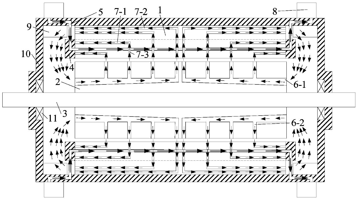
[0031] Specific implementation mode 2: Combining image 3 Describe this embodiment. The difference between this embodiment and Embodiment 1 is that the inlet area of ​​the rotor axial direct cooling air passage 6-1 is increased, and the inlet area is 130 mm. 2 ~400mm 2 , the cross-sectional area of ​​the rotor axial direct cooling air duct 6-1 gradually decreases along the axial direction, which can increase the fluid flow rate entering the rotor core 2, speed up the circulation speed of the cooling gas in the switched reluctance motor, and improve the cooling rate of the cooling gas. The utilization rate of the switched reluctance motor reduces the temperature of the stator core 1, rotor core 2 and stator copper winding 3 inside the switched reluctance motor. Other components and connections are the same as those in Embodiment 1.

specific Embodiment approach 3

[0032] Specific implementation three: combination Figure 4 Describe this embodiment, the difference between this embodiment and Embodiment 1 is that the number of stator direct cooling air passages 7 in the stator core 1 has been increased, the cooling effect of the yoke of the stator core 1 has been enhanced, and the internal temperature of the stator core 1 has been improved. The surface heat dissipation coefficient effectively improves the ability of the cooling gas to take away heat from the stator core 1 and further reduces the temperature of the stator core 1 . Other components and connections are the same as those in Embodiment 1.


PUM


Abstract

The invention discloses a switched reluctance motor with a water injection type winding and an axial-radial-circumferential multi-directional self-circulating ventilation system, which belongs to thetechnical field of motors, and aims to solve the problem of high temperature of the existing large-capacity switched reluctance motor. A rotor shaft is mounted on a base through a bearing, a rotor core is mounted on the rotor shaft, a stator core is mounted on the inner wall of the base, a stator copper winding is mounted on the stator core, the rotor core is located in the stator core and a mounting clearance is reserved between the two, a stator direct cooling water pipe is located in the stator copper winding, the two ends of the stator direct cooling water pipe respectively penetrate through the base and are connected to an inlet and an outlet of a direct cooling water driving device, a rotor direct cooling air passage is provided in the rotor core, a stator direct cooling air passageis provided in the stator core, a flaky heat conduction plate is also arranged on the inner wall of the base, and the flaky heat conduction plate corresponds to the stator direct cooling water drivingdevice outside the base. The cooling effect of each component in the large-capacity switched reluctance motor is enhanced, and the switched reluctance motor is simple in structure and convenient to implement.

Description

technical field [0001] The invention relates to a reluctance motor, in particular to a switched reluctance motor with a water-injection winding and a multi-directional self-circulating ventilation system, and belongs to the technical field of motors. Background technique [0002] The switched reluctance motor has the characteristics of high reliability, low manufacturing cost, and simple and firm structure. Compared with other motors, there are no windings and permanent magnets on the rotor of the switched reluctance motor, which makes the switched reluctance motor more suitable for high temperature and high speed conditions. The switched reluctance motor also has the advantages of small starting current and large starting torque. However, as the capacity of switched reluctance motors continues to increase, the temperature rise of the stator core and stator copper windings of switched reluctance motors increases significantly. The temperature of stator core and stator coppe...

Claims


Application Information

Patent Timeline
Patent Type & Authority Patents(China)
IPC IPC(8): H02K9/08H02K1/20H02K1/32H02K5/18
CPCH02K1/20H02K1/32H02K5/18H02K9/08
Inventor 韩继超王磊孙玉田郑萍戈宝军陶大军吕艳玲白金刚隋义肖芳
Owner HARBIN UNIV OF SCI & TECH
Why Eureka
Try Eureka