
Positive and negative output DC-DC power source structure based on Boost

A DC power supply, positive and negative technology, applied in the direction of output power conversion device, DC power input conversion to DC power output, electrical components, etc., can solve the problems of increasing the volume and cost of the conversion circuit, and achieve space saving and small current ripple , cost-saving effect

Active Publication Date: 2018-10-12
GUANGDONG MECHANICAL & ELECTRICAL COLLEGE
View PDF14 Cites 2 Cited by
  • Summary
  • Abstract
  • Description
  • Claims
  • Application Information

AI Technical Summary

Problems solved by technology

If it is a positive and negative power supply, it is necessary to use an additional switch tube (or switch control chip), or add more than one inductor L to achieve the conversion requirements, which greatly increases the size and cost of the conversion circuit.

Method used


Image

  • Positive and negative output DC-DC power source structure based on Boost
  • Positive and negative output DC-DC power source structure based on Boost
  • Positive and negative output DC-DC power source structure based on Boost

Examples


Embodiment Construction

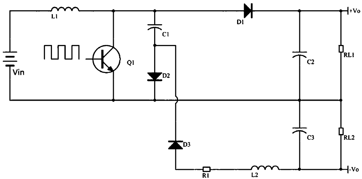
[0015] Transformation circuit structure of the present invention such as figure 1 As shown, a typical Boost transformation structure includes input DC power supply Vin, inductor L1, diode D1, switch tube Q1, and energy storage filter capacitor C2. The positive pole of DC power supply Vin is connected to the collector of switch tube Q1 through inductor L1. The cathode of the switch is connected to the emitter of the switch tube Q1, the base of the switch tube Q1 inputs a square wave signal, the diode D1 is connected in series between the collector of the switch tube Q1 and the positive output terminal, and the energy storage filter capacitor C2 is connected in parallel between the output load RL1 end. The present invention inserts a capacitor C1 and a diode D2 connected in series at the switching node between the inductor L1 and the diode D1 of a typical Boost transformation structure, and then connects the diode D3 and the resistor R1 connected in series at the node connected ...


PUM


Abstract

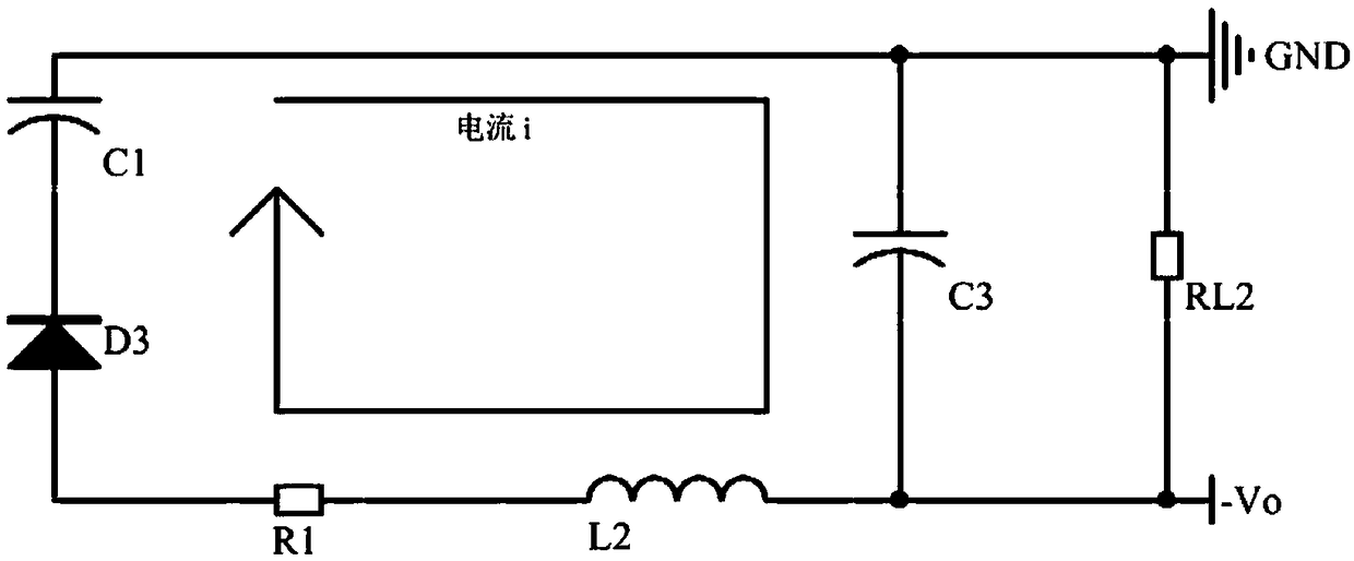
The invention belongs to the technical field of power supply of power sources, and provides a positive and negative output DC-DC power source structure based on Boost. The structure comprises a Boostconversion structure, and the Boost conversion structure comprises an input direct current power source Vin, an inductor L1, a diode D1, a switching tube Q1 and an energy storage filter capacitor C2;a capacitor C1 and a diode D2 which are in series connection with each other are inserted into a switching node between the inductor L1 and the diode D1, and a diode D3, an inductor L2 and an energy storage filter capacitor C3 which are in series connection are connected into a series-connection node of the capacitor C1 and the diode D2, and two output ends of negative voltage are draw forth fromthe two ends of the energy storage filter capacitor C3; a negative electrode of the diode D3 is connected with the capacitor C1, a positive electrode of the diode D2 is connected with the capacitor C1, and the capacitor C1, the inductor L2 and the energy storage filter capacitor C3 constitute an LC filter circuit. By means of the positive and negative output DC-DC power source structure, a switching tube or a switching control chip does not need to be additionally arranged, the circuit structure is simple, and the cost is low; the structure has a high current output capability and small current pulsation, and the positive voltage and negative voltage are nearly symmetric.

Description

technical field [0001] The invention relates to the technical field of power supply, in particular to a DC-DC power supply structure based on Boost positive and negative outputs. Background technique [0002] In most electronic circuits, a single power supply is generally used, and in order to better utilize the accuracy of the amplifier circuit, it is generally necessary to use a positive and negative boost power supply system. The current solutions generally use Boost, Buck-Boost, Cuk, Sepic and other circuit transformation structures. Among them, Boost is a positive boost conversion structure, Sepic is a positive buck-boost structure, Cuk, Buck-Boost is a negative boost structure, and these conversion structures must use at least one or more switching tubes (or switch control chips), inductors L, Diode D and capacitor C. If it is a positive and negative power supply, it is necessary to use one more switch tube (or switch control chip), or add more than one inductance L ...

Claims


Application Information

Patent Timeline
Patent Type & Authority Applications(China)
IPC IPC(8): H02M3/156
CPCH02M3/156Y02B70/10
Inventor 丘李旺涂祥邝柏超
Owner GUANGDONG MECHANICAL & ELECTRICAL COLLEGE
Learn More