
Fuel heater

A fuel heater and fuel technology, which is applied to heating/cooling equipment, machines/engines, air handling equipment, etc., can solve the problems of uneven intake air distribution, large flue gas flow resistance, and easy generation of flocculation, and achieve improvement. Vaporization ignition conditions and combustion conditions, improving the utilization rate of heat, and improving the effect of ignition conditions

Pending Publication Date: 2018-10-16
中山劲牛科技有限公司 +1
View PDF6 Cites 5 Cited by
  • Summary
  • Abstract
  • Description
  • Claims
  • Application Information

AI Technical Summary

Problems solved by technology

[0005] 1. Due to the low temperature of the air supplied to the vaporization mechanism and the combustion chamber, the vaporization ignition and combustion conditions are poor
[0006] 2. The holes used to allow air to enter the combustion chamber make the distribution of air intake uneven, and the surrounding area is prone to flocculation, which makes the combustion efficiency in the combustion chamber unsatisfactory
[0007] 3. The flue gas flow resistance in the combustion chamber is relatively large, so the requirements for the heat intensity of the parts surrounding the combustion chamber are high
[0008] 4. The vaporization mechanism and the combustion mechanism are welded and formed, which causes residual stress and deformation at the joint, thereby reducing manufacturing accuracy, and has the disadvantage of cracking at the weld
[0009] 5. The internal parts of the vaporization mechanism need to be replaced frequently due to the easy generation of carbon deposits. However, the vaporization mechanism in the prior art is poor in maintainability and replaceability

Method used


Image

  • Fuel heater
  • Fuel heater
  • Fuel heater

Examples


Embodiment Construction

[0046] Exemplary embodiments of the present invention will be described in detail below with reference to the accompanying drawings. The description of the exemplary embodiments is for the purpose of illustration only, and in no way limits the invention and its application or usage.

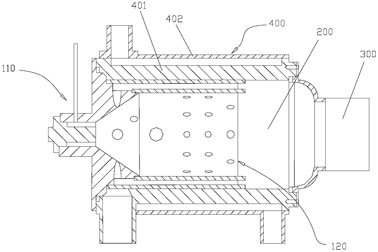
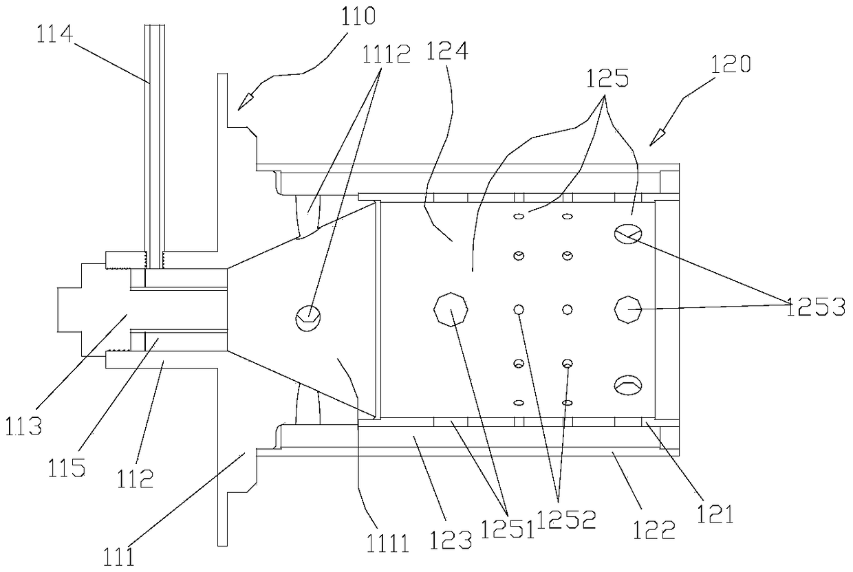
[0047] Such as figure 1 and figure 2 As shown, the embodiment of the present invention discloses a fuel heater, which includes a vaporization mechanism 110 , a combustion mechanism 120 , an air blowing mechanism 300 and a heat exchange mechanism 400 . The combustion mechanism 120 has a combustion chamber 124, the vaporization mechanism 110 is used to provide vaporized fuel for the combustion chamber 124 so that the fuel is combusted in the combustion chamber 124; the blower mechanism 300 is used to provide air for the combustion chamber 124 and the vaporization mechanism 110; the heat exchange mechanism 400 is used to export the heat generated by fuel combustion. Wherein: the combustion chamb...


PUM


Abstract

The invention discloses a fuel heater which comprises a gasification mechanism, a combustion mechanism, a blasting mechanism and a heat exchange mechanism. The gasification mechanism is used for supplying gasified fuel to a combustion chamber to enable the fuel to be combusted in the combustion chamber. The blasting mechanism is used for supplying air to the combustion chamber and the gasificationmechanism. The combustion chamber is surrounded by a gas inlet channel, and the gas inlet channel communicates with the combustion chamber to enable the air in the air inlet channel to flow oppositely with the fuel and flames in the combustion chamber. The blasting mechanism enables the air to enter the air inlet channel, the flowing direction of the air in the air inlet channel is opposite to the flowing direction of the combusting fuel and the flames in the combustion chamber, and heat generated by fuel combustion is rightly used for preheating the air opposite to the direction of a fuel flow channel, so that the air in the air inlet channel is preheated and then enter the combustion chamber. Accordingly, the temperature of the air mixed with the gasified fuel is improved, the gasification ignition condition and the combustion condition are improved, and the burn-off rate of the fuel is improved.

Description

technical field [0001] The invention relates to the technical field of automobiles, and in particular provides a fuel heater for heating the engine of the automobile or the interior of the cab of the automobile. Background technique [0002] In cold regions such as Northeast China, North China and Northwest China, it is difficult to start the car at low temperature in winter, which will cause great damage to the engine. Fuel heaters are usually used to raise the temperature to solve this problem. [0003] A fuel oil heater in the prior art generally includes a vaporization mechanism, a combustion mechanism, an air blast mechanism and a heat exchange mechanism. Among them, the vaporization mechanism is used to vaporize the fuel, the combustion mechanism is used to burn the vaporized fuel in the combustion chamber, the blower mechanism provides air for the combustion chamber and the vaporization mechanism, and the heat exchange mechanism is used to provide the heat generated b...

Claims


Application Information

Patent Timeline
Patent Type & Authority Applications(China)
IPC IPC(8): B60H1/22F02N19/02
CPCF02N19/02B60H1/2203B60H2001/2271
Inventor 邱朋华王辉尹志臣郭炫谟孙静怡刘彦甫齐宝恒
Owner 中山劲牛科技有限公司
Learn More