Method for calculating cable interference in infinite shielding layer with holes in point source radiation field

A calculation method and radiation field technology, applied in the measurement of interference from external sources, measurement devices, instruments, etc., can solve problems such as difficulty in implementation, time-consuming and computational resources, and computational complexity, and achieve concise algorithms, accurate calculations, and results. accurate effect

Inactive Publication Date: 2018-10-16
UNIV OF ELECTRONICS SCI & TECH OF CHINA
View PDF6 Cites 6 Cited by
  • Summary
  • Abstract
  • Description
  • Claims
  • Application Information

AI Technical Summary

Problems solved by technology

This method is of great significance in the field of electromagnetic interference calculation, but there are still some shortcomings
[0005] ① This method is a numerical method, which consumes a lot of time and computing resources;
[0006] ② This method deals with the field line coupling problem with the help of multi-conductor transmission line theory, which requires the combined use of FDTD, multi-conductor transmission line theory, etc., and the calculation is complicated and difficult to implement;
[0007] ③This method requires a series of pre-processing work such as modeling, meshing, and boundary imposition, which is relatively troublesome to implement
[0009] ① This method does not consider the small hole coupling of the electromagnetic field, and cannot be used for the coupling analysis of the actual electronic equipment chassis and the calculation of the electromagnetic interference intensity;
[0010] ②The focus of this method is to give the method of establishing the system extended BLT equation, and does not give the specific calculation method of the scattering parameters of the infinitely large shielding layer with holes;
[0011] ③This method is suitable for open-domain electromagnetic field coupling problems, but not for closed-domain electromagnetic field coupling problems

Method used


Image

  • Method for calculating cable interference in infinite shielding layer with holes in point source radiation field
  • Method for calculating cable interference in infinite shielding layer with holes in point source radiation field
  • Method for calculating cable interference in infinite shielding layer with holes in point source radiation field

Examples


Embodiment Construction

[0031] In order to make the object, technical solution and advantages of the present invention clearer, the present invention will be further described in detail below in conjunction with the accompanying drawings and embodiments. It should be understood that the specific embodiments described here are only used to explain the present invention, not to limit the present invention.

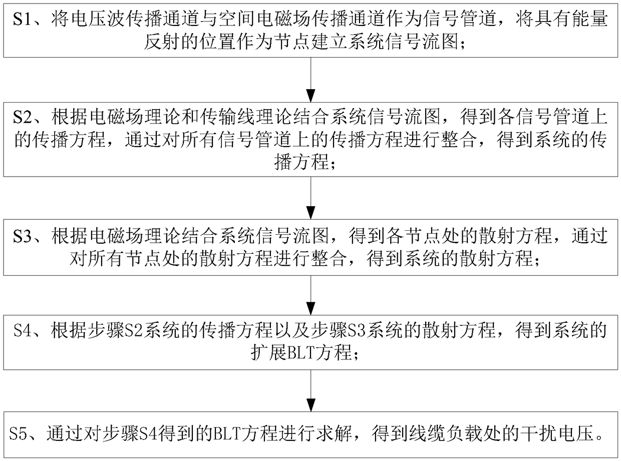
[0032] Such as figure 1 Shown is the scheme flow chart of the present invention, and the technical scheme of the present invention is: the calculation method of the interference of the point source radiation field to the cable in the infinitely large shielding layer with holes, including:

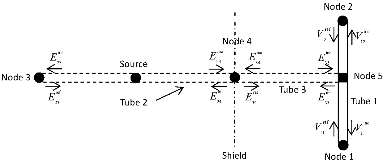
[0033] S1. The voltage wave propagation channel and the space electromagnetic field propagation channel are used as signal pipelines, and the positions with energy reflection are used as nodes to establish a system signal flow diagram; specifically as figure 2 As shown, the cable in the present invention is co...


PUM


Abstract

The invention discloses a method for calculating cable interference in an infinite shielding layer with holes in a point source radiation field, is applied to the field of electromagnetic interference, and has the advantages of simple algorithm, accurate result, high efficiency and the like. In that method, the aisle of the voltage wave on the cable and the propagation aisle of the space electromagnetic field are represented by signal pipelines, the position with the energy reflection is represented by nodes, a signal flow graph reflecting the electromagnetic energy flow of the system is established, the propagation equation of the whole system signal pipeline and the scattering equation on all the nodes are established by using the magnetic flow element radiation instead of the small holetransmission, the extended BLT (Baum-Liu-Tesche) equation of the system electromagnetic interference is obtained, and the interference intensity on the cable is obtained by solving the extended BLT equation. The method realizes the accurate calculation of the electromagnetic interference of the point source radiation field in the infinite shielding layer with holes and is coupled to the transmission line, and the method effectively reduces the dependence on the computing resources and improves the efficiency.

Description

technical field [0001] The invention belongs to the field of electromagnetic interference, in particular to a method for calculating the interference of a point source radiation field to a cable on the other side of an infinitely large shielding layer with a hole. Background technique [0002] With the increasing electrification of industry and the development of wireless communication technology, the complexity of the electromagnetic environment has increased exponentially. External electromagnetic waves can be coupled to cables inside the device through small holes in the case of the electronic device, causing electromagnetic interference (EMI) to sensitive circuits. Interference intensity can be measured by the voltage amplitude induced on the cable, which is affected by the characteristics of the interference source, hole size, cable structure and their relative position. According to the electromagnetic field theory, the complex interference source can be regarded as t...

Claims


Application Information

Patent Timeline
Patent Type & Authority Applications(China)
IPC IPC(8): G01R31/00
CPCG01R31/001
Inventor 聂宝林杜平安
Owner UNIV OF ELECTRONICS SCI & TECH OF CHINA
Why Eureka
Try Eureka