Thermal treatment device for metal

A metal heat treatment and equipment technology, applied in the field of heat treatment, can solve the problems of reducing heat treatment quality and heat treatment efficiency, affecting the heat treatment effect of metal workpieces, affecting the process quality of metal workpieces, etc., to avoid heat transfer and heat loss, reduce heat loss, improve Effect of heat treatment quality

Pending Publication Date: 2018-10-19
海安金锻工业有限公司
View PDF6 Cites 6 Cited by
  • Summary
  • Abstract
  • Description
  • Claims
  • Application Information

AI Technical Summary

Problems solved by technology

[0003] When the metal workpiece is transferred from the outlet of the heating furnace to the cooling equipment, the hot air in the heating furnace is output from the outlet of the heating furnace, causing heat loss, and the cold air from the outside and the cold air in the cooling equipment can easily When entering the heating furnace from the discharge port of the heating furnace, the heating efficiency in the heating furnace will be reduced, causing energy waste, and affecting the heat treatment effect of the metal workpiece, reducing the heat treatment quality and heat treatment efficiency
[0004] In the prior art, the height of the heating furnace is mostly higher than that of the cooling equipment. After the metal workpiece is heated, it cannot withstand a large impact force. Due to the height difference, the conveying device in the cooling zone directly falls onto the conveying device in the cooling zone and is impacted, so that the surface of the metal workpiece that has just been heated is damaged to a certain extent, which affects the process quality of the metal workpiece
When the metal workpiece is transported from the cooling area to the finished product warehouse, the metal workpiece is also vulnerable to damage due to the height difference between the cooling equipment and the finished product warehouse

Method used


Image

  • Thermal treatment device for metal
  • Thermal treatment device for metal
  • Thermal treatment device for metal

Examples


Embodiment 1

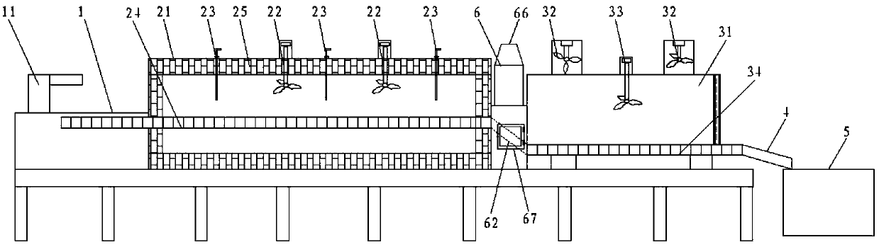
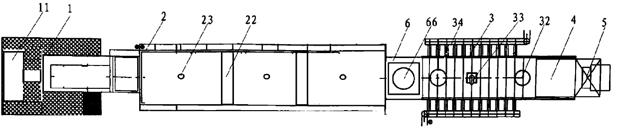
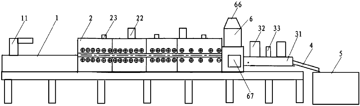
[0052] This embodiment provides a metal heat treatment equipment, such as figure 1 , figure 2 and image 3 As shown, it includes a feeding area, a heating area and a cooling area arranged in sequence, and a discharge buffer zone is provided between the heating area and the cooling area.

[0053] The feeding area is connected to the feeding end of the heating area, and the feeding area includes a feeding platform 1, on which a feeding manipulator 11 is arranged, which reduces the labor intensity of workers and improves production efficiency.

[0054] The heating zone includes a heating furnace 2, and the heating furnace 2 includes an electric heating system or a fuel heating system. Preferably, in this embodiment, the heating furnace 2 adopts an electric heating system;

[0055] Specifically, the heating furnace 2 includes a furnace body 21, a first stirring fan 22, a temperature detection device 23 and a first conveying device 24 for transporting workpieces. The furnace bod...

Embodiment 2

[0070] The structure of the metal heat treatment equipment provided in this embodiment is basically the same as that in Embodiment 1, except that the structure of the first closing curtain 631 is different. A first closing curtain 631 is provided at the feeding port 63 of the buffer zone, and the first closing curtain 631 effectively blocks the outflow of internal air and the inflow of external air. Preferably, the first closed curtain 631 is a metal curtain, and the first closed curtain 631 includes a plurality of curtain panels 632 arranged side by side continuously, and the top of the curtain panels 632 is connected to the bottom of the buffer zone feeding port 64. The top edge is hinged, and the bottom end of the curtain plate 632 can be in contact with the surface of the inclined plate. Wherein, the curtain plate 632 includes a plurality of curtain plate monomers 633, and two adjacent curtain plate monomers 633 are hinged. The curtain plate 632 is divided into a pluralit...


PUM


Abstract

The invention discloses a thermal treatment device for a metal. The device comprises a heating area, a discharging buffering area and a cooling area which are sequentially arranged, wherein the heating area comprises a heating furnace; the cooling area comprises a cooling device; the discharging buffering area comprises a discharging buffering device, and the discharging buffering device comprisesa protecting cover, and a guide mechanism which is arranged in the protecting cover; a buffering area feeding port and a buffering area discharging port are formed in the outer side of the protectingcover; the buffering area feeding port communicates with a discharging port of the heating furnace; the buffering area discharging port communicates with a feeding port of the cooling device; one endof the guide mechanism is connected to the buffering area feeding port, and the other end of the guide mechanism is connected to the buffering area discharging port. The thermal treatment device forthe metal is compact and ingenious in structure, high in reliability, and high in automation degree; the discharging buffering device is additionally arranged, so that outside cold air can be effectively prevented from directly entering the heating area, and as a result, the heat loss is decreased; the heat transfer between the heating area and the cooling area is avoided; the heating efficiency and the thermal treatment quality are improved; and moreover, the workpiece damage is reduced; and the product quality is improved.

Description

technical field [0001] The invention relates to the technical field of heat treatment, in particular to metal heat treatment equipment. Background technique [0002] Metal heat treatment is to heat a metal workpiece in a certain medium to a suitable temperature, and keep it at this temperature for a certain period of time, then cool it at a different speed, and control its performance by changing the surface or internal structure of the metal material. kind of craft. Heat treatment equipment is equipment for annealing, tempering, quenching, heating and other heat treatment operations on metal workpieces. The existing heat treatment equipment includes two working areas of heating and cooling. The metal workpiece is heated by the heating furnace, and then sent to the cooling area for cooling by the cooling equipment. After the metal workpiece is processed, it is sent out by the conveyor belt and directly from the discharge port. Dropped into finished product bin. [0003] W...

Claims


Application Information

Patent Timeline
Patent Type & Authority Applications(China)
IPC IPC(8): C21D1/00C21D9/00C21D11/00
CPCC21D1/00C21D9/0018C21D9/0062C21D11/00
Inventor 何洪均
Owner 海安金锻工业有限公司
Why Eureka
Try Eureka