A Highly Selective Dual-Passband Power Divider Filter

A high-selectivity, dual-passband technology, applied in the direction of waveguide devices, circuits, electrical components, etc., can solve the problems of increasing the difficulty of implementing cross-coupling topology, poor isolation level, poor selectivity, etc., to achieve easy processing integration, Low production cost and good isolation effect

Active Publication Date: 2020-01-03
NANJING NORMAL UNIVERSITY
View PDF8 Cites 0 Cited by
  • Summary
  • Abstract
  • Description
  • Claims
  • Application Information

AI Technical Summary

Problems solved by technology

[0003] Document 1 [C.F.Chen, T.Y.Huang, T.M.Shen and R.B.Wu, "Design of Miniaturized Filtering Power Dividers for System-in-a-Package," IEEE Transactions on Components, Packaging and Manufacturing Technology, vol.3, no.10, pp. 1663-1672, Oct.2013] A Wilkinson power divider with Chebyshev and quasi-elliptic bandpass responses was implemented by utilizing mesh resonators, however, in order to improve the in-band isolation characteristics of the higher order responses , this kind of power dividing filter needs multi-layer isolation resistors to realize, which increases the difficulty of realizing the cross-coupling topology
[0004] Document 2 [X.Wang, J.Wang, G.Zhang, J.S.Hong and W.Wu, "Dual-wideband filtering power divider with good isolation and high selectivity," IEEE Microw.Wireless Compon. Lett., vol.27, no. 12, pp.1071-1073, Dec.2017] proposed a dual-passband power division filter with wide stopband performance, however, the problems of large insertion loss and poor selectivity limit the wide application of the power division filter application
[0005] Document 3 [S.S.Gao, S.Sun and S.Xiao, "A Novel Wideband Bandpass PowerDivider With Harmonic-Suppressed Ring Resonator," IEEE Microwave and Wireless Components Letters, vol.23, no.3, pp.119-121, March 2013 ] By using a ring resonator, a high-selectivity broadband power divider filter is designed, but its in-band isolation level is not good

Method used


Image

  • A Highly Selective Dual-Passband Power Divider Filter
  • A Highly Selective Dual-Passband Power Divider Filter
  • A Highly Selective Dual-Passband Power Divider Filter

Examples


Embodiment 1

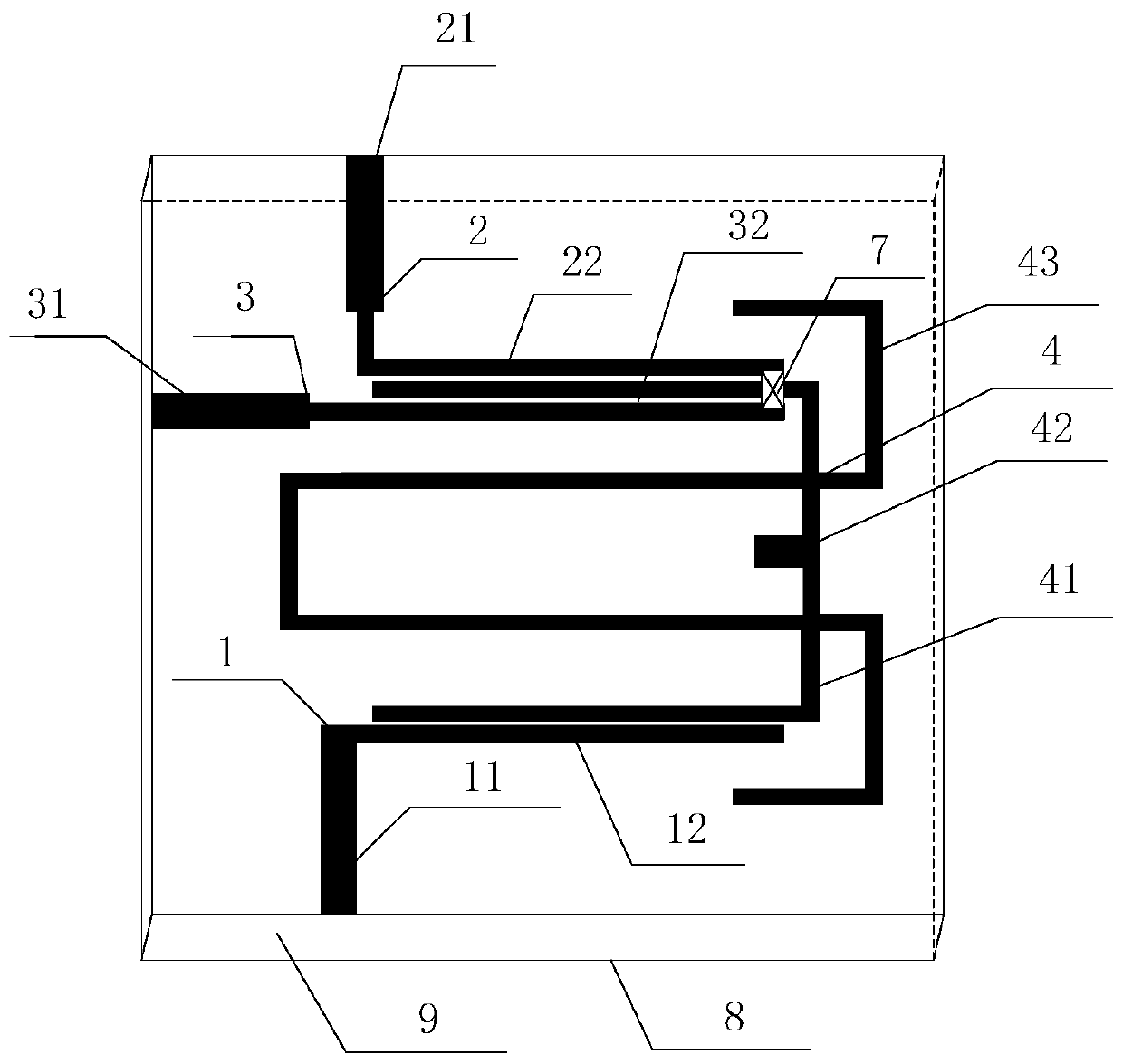
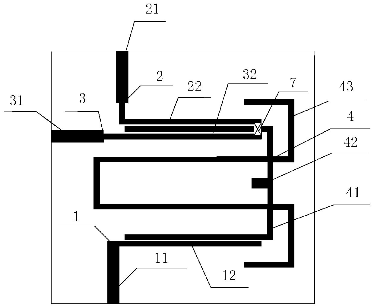
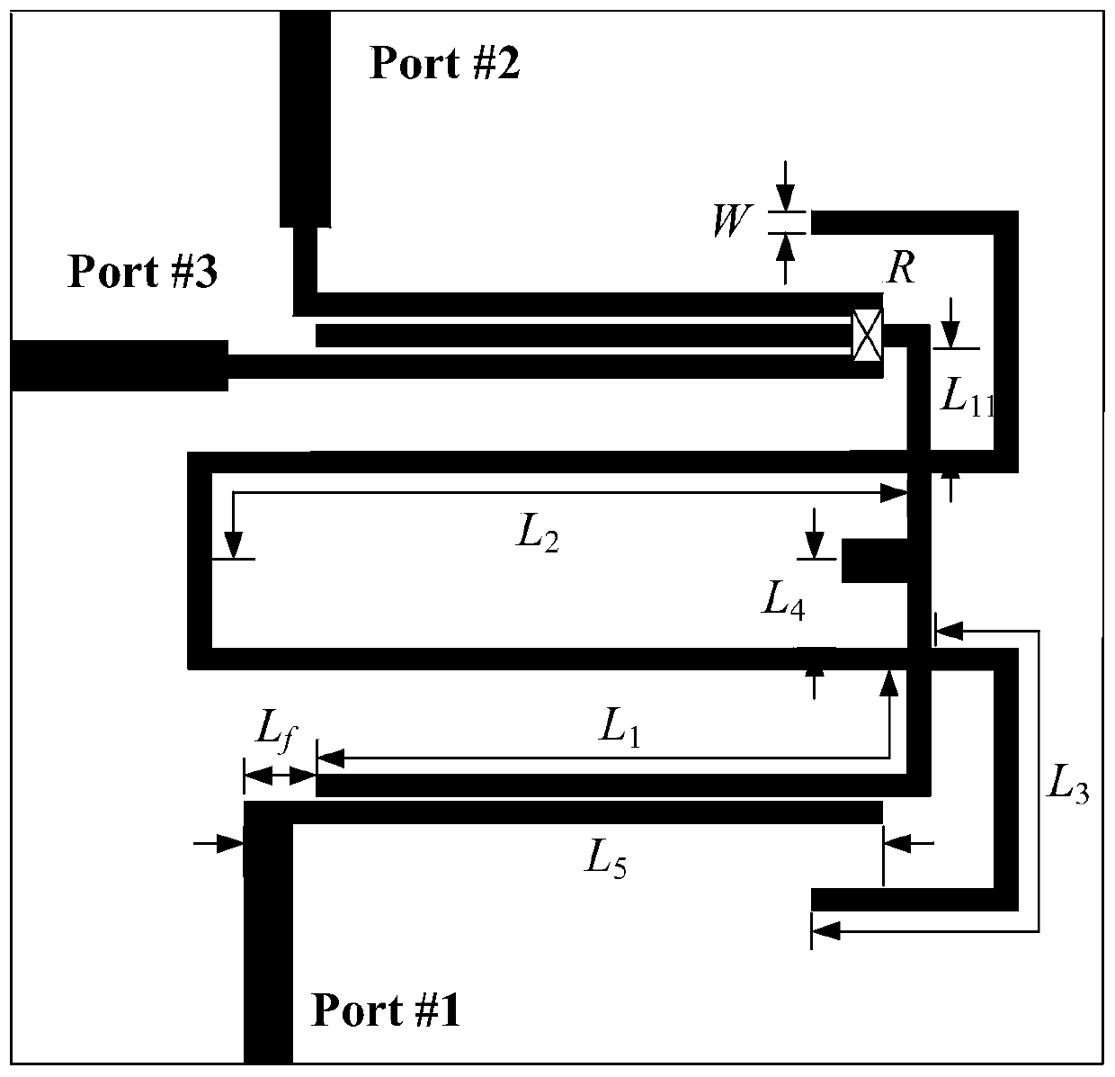
[0052] The structure of a high-selectivity dual-passband power division filter is as follows: figure 1 As shown, the top view is as figure 2 As shown, the relevant dimensions and specifications are as follows image 3 shown. The dielectric substrate 9 used has a relative permittivity of 3.55, a thickness of 0.508 mm, and a loss tangent of 0.0027. combine image 3 , the size parameters of the power division filter are as follows: L 11 =16.0mm,L 11 =2.4mm,L 2 =18.5mm,L 3 =12mm,L 4 =2mm,L 5 =1.1mm,L f =1.5mm, W=0.5mm, g 1 =0.1mm,g 2 =0.2mm and R=190Ω.

[0053] The power dividing filter of this example is modeled and simulated in the electromagnetic simulation software HFSS.13.0. Figure 4 It is the S-parameter simulation of the power division filter in this example and the physical waveform diagram with the processed object. It can be seen from the figure that the passband center frequencies of the dual-passband power division filter are 2.41GHz and 3.63GHz respecti...


PUM

PropertyMeasurementUnit
thicknessaaaaaaaaaa

Abstract

The invention discloses a high-selectivity double-passband power dividing filter, comprising a polygonal dielectric substrate provided with a metal grounding plate on a lower surface thereof. An inputport feeding line, a first output port feeding line, a second output port feeding line, a first output coupling line and a second output coupling line are arranged on the upper surface of the polygonal dielectric substrate. The first output port feeding line and the second output port feeding line are close to two vertically-adjacent edges of the polygonal dielectric substrate. A branch-loading type multi-mode resonator is arranged between the first output port feeding line and the second output port feeding line. An isolation resistor is arranged between the first output coupling line and the second output coupling line. The high-selectivity double-passband power split filter is compact in structure, low in loss, high in selectivity, good in isolation and good in out-of-band rejection performance.

Description

technical field [0001] The invention relates to the technical field of microwave passive devices, in particular to a high-selectivity dual-pass band power divider filter with multiple characteristics such as compact structure, low loss, high selectivity, good isolation, and good out-of-band suppression. . Background technique [0002] In recent years, with the development of Modular Building Block (MBB) and Monolithic Microwave Integrated Circuit (MMIC), low cost, high integration, and miniaturization have become very important in the integrated design of modern wireless communication systems. important consideration. Usually, the RF front-end circuit is composed of different devices, such as filters, power splitters, etc., and designing these devices separately will undoubtedly increase the physical size of the front-end circuit. The most efficient way to size. As a functionally integrated passive component, the power divider filter has attracted extensive attention from...

Claims


Application Information

Patent Timeline
Patent Type & Authority Patents(China)
IPC IPC(8): H01P1/203
CPCH01P1/203
Inventor 张钢钱振耀
Owner NANJING NORMAL UNIVERSITY
Why Eureka
Try Eureka