High-efficient continuous F-class power amplifier based on transistor stacking technology

A technology for power amplifiers and power amplification, applied in power amplifiers, amplifiers with semiconductor devices/discharge tubes, amplifiers, etc., can solve the problems of low power output capability and power gain capability, mutual constraints of ultra-wideband high-efficiency indicators, and broadband output Capability and efficiency are low, to achieve good input and output matching, simplify the peripheral grid power supply structure, improve power capacity and power gain

Pending Publication Date: 2018-10-19
CHENGDU GANIDE TECH
View PDF15 Cites 0 Cited by
  • Summary
  • Abstract
  • Description
  • Claims
  • Application Information

AI Technical Summary

Problems solved by technology

However, in the design of traditional high-efficiency power amplifiers, there have always been some design problems, mainly reflected in the mutual restriction of ultra-wideband and high-efficiency indicators: in order to ensure the high-efficiency operation of the amplifier, the transistor must work in the overdrive mode, similar to the switch state, but the bandwidth of the overdrive switching power amplifier has always been the technical bottleneck of the circuit implementation
[0003] There are many circuit structures of common high-efficiency power amplifiers, the most typical ones are traditional class AB, class C, switching type power amplifiers of class D, class E, and class F, etc. However, there are still some shortcomings in the broadband characteristics of these high-efficiency amplifiers. , which is mainly reflected in: the theoretical limit efficiency of the traditional class AB amplifier is 78.5%, which is relatively low, and it is often necessary to sacrifice the output insertion loss and efficiency to increase the bandwidth of the amplifier; the limit efficiency of the class C amplifier is 100%, but the power output capability is low. The broadband output capability and efficiency are low; switching type D, E, F power amplifiers, etc. need to rely on precise harmonic impedance control, or strict impedance matching conditions, these controls and conditions greatly limit the operating bandwidth of the amplifier
In addition, the existing high-efficiency FET power amplifiers are often implemented based on a single common-source transistor, which is limited by a single transistor, and the power output capability and power gain capability are relatively low

Method used


Image

  • High-efficient continuous F-class power amplifier based on transistor stacking technology
  • High-efficient continuous F-class power amplifier based on transistor stacking technology

Examples


Embodiment Construction

[0019] Exemplary embodiments of the present invention will now be described in detail with reference to the accompanying drawings. It should be understood that the implementations shown and described in the drawings are only exemplary, intended to explain the principle and spirit of the present invention, rather than limit the scope of the present invention.

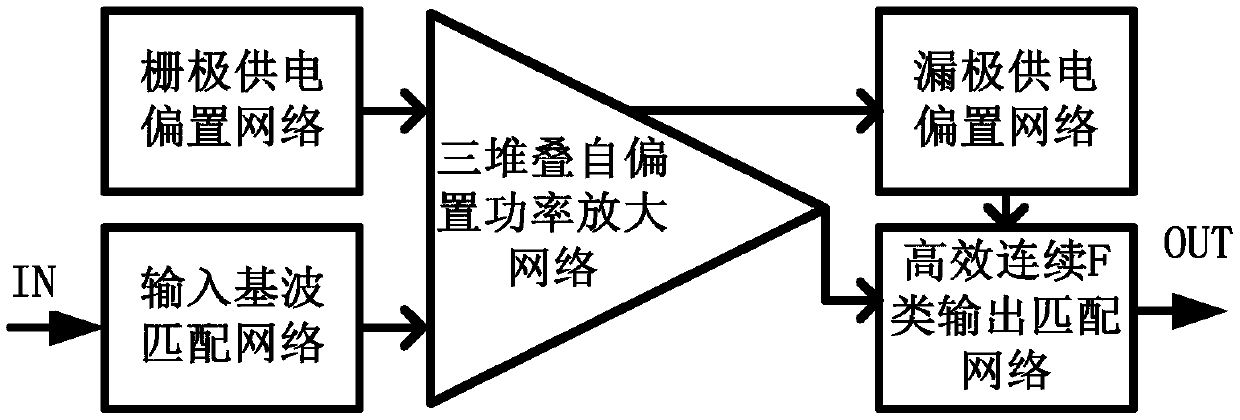
[0020] An embodiment of the present invention provides a high-efficiency continuous class F power amplifier based on transistor stacking technology, such as figure 1 As shown, including input fundamental wave matching network, three-stack self-biased power amplifier network, high-efficiency continuous class F output matching network, gate supply bias network and drain supply bias network; the input terminal of the input fundamental wave matching network is The input end of the entire high-efficiency continuous class F power amplifier is connected to the input end of the three-stacked self-biased power amplification netwo...


PUM


Abstract

The invention discloses a high-efficient continuous F-class power amplifier based on transistor stacking technology. The F-class power amplifier comprises an input fundamental wave matching network, athree-stacked self-bias power amplification network, an efficient continuous F-class output matching network, a grid power supply bias network and a drain power supply bias network. By adopting the three-stacked transistor structure based on the self-bias structure and combining with the efficient continuous F-class output matching network, the circuit has high efficiency, high gain and high power output capacity of the ultra-wide band and has good input-output matching, and the additional stacked grid bias circuit is unnecessary at the same time.

Description

technical field [0001] The invention belongs to the technical field of field effect transistor radio frequency power amplifiers and integrated circuits, and in particular relates to the design of a high-efficiency continuous class F power amplifier based on transistor stacking technology. Background technique [0002] With the development of modern military and civilian communication technologies, RF front-end transmitters are also developing in the direction of ultra-wideband, high efficiency, high gain, and high power output. Therefore, the market urgently needs ultra-wideband, high-efficiency, high-gain, and high-power power amplifiers. However, in the design of traditional high-efficiency power amplifiers, there have always been some design problems, mainly reflected in the mutual restriction of ultra-wideband and high-efficiency indicators: in order to ensure the high-efficiency operation of the amplifier, the transistor must work in the overdrive mode, similar to the s...

Claims


Application Information

Patent Timeline
Patent Type & Authority Applications(China)
IPC IPC(8): H03F3/217H03F1/56H03F3/24H03F3/193
CPCH03F1/56H03F3/193H03F3/2171H03F3/245H03F2200/451
Inventor 童伟邬海峰滑育楠陈依军胡柳林吕继平王测天
Owner CHENGDU GANIDE TECH
Why Eureka
Try Eureka