Preparation method of composite air cylinder

A technology of composite materials and composite material layers, which is applied in the field of composite material pressure vessel manufacturing, can solve the problems of excessive load strength in the head area, conservative design of head strength, and failure to consider the strength of the inner liner head, etc.

Active Publication Date: 2018-10-23
AEROSPACE RES INST OF MATERIAL & PROCESSING TECH +1
View PDF9 Cites 5 Cited by
  • Summary
  • Abstract
  • Description
  • Claims
  • Application Information

AI Technical Summary

Problems solved by technology

[0004] Although the multi-angle step-by-step reaming winding not only makes the shape change of the head more gentle, avoids excessive accumulation and overhead of fibers, but also distributes the strength of the fibers of each winding angle accumulated at the pole hole more evenly, effectively reducing the The weight at the head of the composite gas cylinder, bu

Method used


Image

  • Preparation method of composite air cylinder

Examples


preparation example Construction

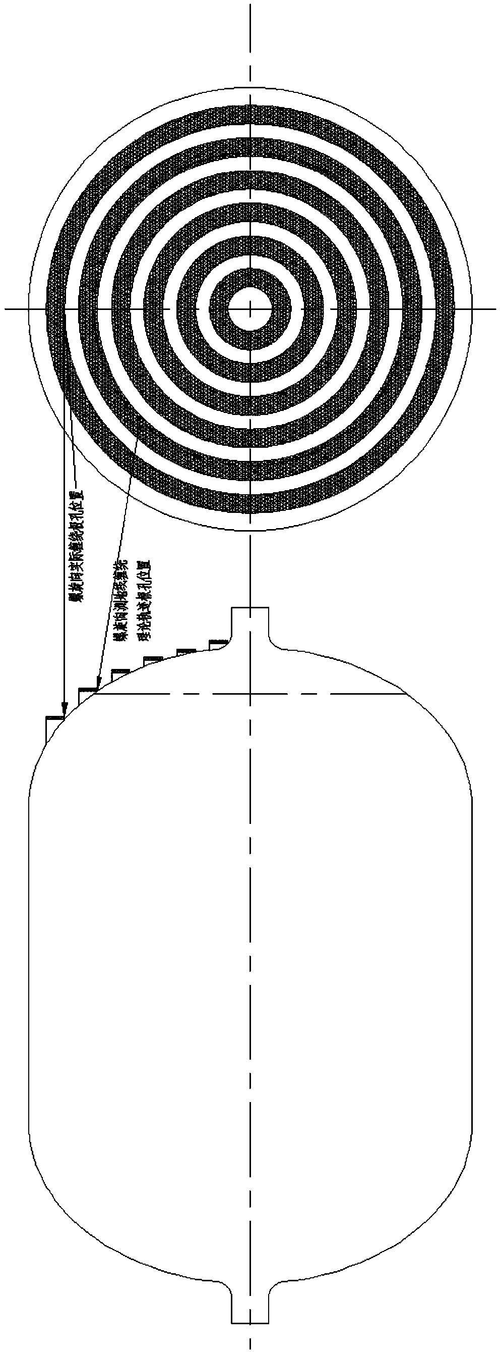
[0030] A preparation method of a composite material gas cylinder, the composite material gas cylinder includes an aluminum alloy lining and a composite material layer; the steps of the method include:

[0031] (1) According to the design requirements of the composite gas cylinder, carry out the strength design of the composite material layer of the composite gas cylinder;

[0032] (2) Lay-up design is carried out for each winding layer according to the geodesic method, and the adjacent spiral winding layer is wound with head reaming according to 1.2-1.3 times the bandwidth, and the strength of the barrel section is checked;

[0033] (3) According to the theory of gas cylinder design, the strength of the head composite material layer is higher than that of the cylinder body, and the bearing capacity of the inner liner head is not considered in the strength design process, resulting in excess strength of the gas cylinder head. The thickness of the material layer achieves the pur...

Embodiment

[0040] A preparation method of a composite material gas cylinder, the composite material gas cylinder includes an aluminum alloy lining and a composite material layer; the steps of the method include:

[0041] (1) The design strength of a 9L composite material gas cylinder is 70MPa, the outer diameter of the inner lining is 167mm, the length is 516mm, and the reinforcing fiber is T1000.

[0042] (2) Each winding layer is designed according to the geodesic method, and the adjacent spiral winding layer is wound with head reaming according to 1.2-1.3 times the bandwidth, and the laying sequence is ±90° 2 / ±11° / ±90° / ±16° / ±90° / ±21° / ±90° / ±27° / ±90° / ±33°;

[0043](3) Keep the original winding angle in the barrel section, and carry out head reaming winding in the head area according to 1.6-1.7 times the bandwidth, and the head winding angle becomes 11°, 18°, 25°, 33° and 42°;

[0044] (4) Winding molding is carried out according to the layup angle and layup sequence described in (2) a...


PUM

PropertyMeasurementUnit
Burst strengthaaaaaaaaaa

Abstract

The invention relates to a preparation method of a composite air cylinder and relates to the technical field of manufacturing of composite pressure vessels. The preparation method of the composite aircylinder comprises the steps that a step-by-step broaching mode is adopted for winding layers in the spiral direction of the composite air cylinder, and various winding angles are determined according to the linear trajectory of a geodesic line; and in the winding process, a non-geodesic line winding mode is adopted, variable-angle variable-speed-ratio winding is carried out on an end socket section, and variable-pitch winding is carried out on an edge area of a cylinder body section. Thus, the winding angles of various points of the end socket area are relatively increased, the difference between the internal radius and the external radius of each 'fiber stacking ring' is increased to 1.5-2 times of the actual yarn sheet width, an end socket approaches the uniform thickness, the surplusmass of the end socket can be reduced effectively, the characteristic coefficient of the vessel is increased, and the lightweight purpose of the air cylinder is realized.

Description

technical field [0001] The invention relates to a method for preparing a composite material gas cylinder, belonging to the technical field of composite material pressure vessel manufacturing. Background technique [0002] Composite gas cylinders have the advantages of light weight, high pressure tolerance, high reliability, fatigue resistance, and corrosion resistance. They are ideal lightweight, high-strength, and high-performance gas cylinders, which can meet the requirements of high efficiency and weight reduction for aerospace components. . Composite gas cylinders have been used in spacecraft systems such as launch vehicles, space shuttles, artificial satellites, and space stations at home and abroad, such as: HS2601, HS2702 satellite platforms, the upper stage of Centaur launch vehicles, and domestic XX-5 and XX-7 launch vehicles Wait. The huge cost and potential technical risks required for the successful launch of a spacecraft place stringent requirements on composi...

Claims


Application Information

Patent Timeline
IPC IPC(8): F17C1/06F17C13/00F17C13/06B29C53/58
CPCB29C53/58F17C1/06F17C13/002F17C13/06F17C2201/0109F17C2201/032F17C2201/056F17C2203/067F17C2205/0311F17C2209/2163F17C2270/0197
Inventor 郑红飞张建宝孙宏杰陈亮李文斌
Owner AEROSPACE RES INST OF MATERIAL & PROCESSING TECH
Why Eureka
Try Eureka