Laser bars having trenches

A technology of laser rods and grooves, which is applied in the field of laser rods, can solve problems such as fractures and achieve the effect of avoiding electrical short circuits

Active Publication Date: 2018-10-23
OSRAM OPTO SEMICON GMBH & CO OHG
View PDF14 Cites 3 Cited by
  • Summary
  • Abstract
  • Description
  • Claims
  • Application Information

AI Technical Summary

Problems solved by technology

After welding the laser bar onto a heat sink with a smaller coefficient of expansion and

Method used


Image

  • Laser bars having trenches
  • Laser bars having trenches
  • Laser bars having trenches

Examples


Embodiment Construction

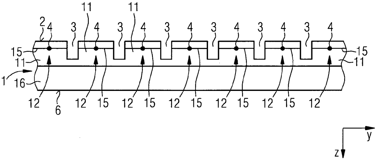
[0035] figure 1 A schematic cross-sectional view of the laser bar 1 is shown. The laser bar 1 has grooves 3 on the first side 2 . The grooves 3 are oriented along the x-axis perpendicular to the drawing plane. The grooves 3 extend to a predetermined depth in the z-axis. Furthermore, the grooves 3 have a predetermined width in the y-axis. The width of the trenches 3 is in the range of 1 μm to 100 μm, preferably 50 μm. The depth of the trenches 3 is in the range of 0.1 μm to 10 μm, preferably 5 μm. In the upper region, the laser rod 1 has a semiconductor layer 11 with a plurality of layers, which is arranged in the xy plane and has an active region 15 for generating electromagnetic radiation. The semiconductor layer 11 is arranged on the substrate 16 . Depending on the chosen embodiment, the trenches 3 can lead under the active area 15 of the semiconductor layer 11 . Furthermore, the grooves 3 can be guided into the base plate 16 . Depending on the chosen embodiment, the...


PUM

PropertyMeasurementUnit
Widthaaaaaaaaaa

Abstract

The invention relates to a laser bar (1) comprising a semiconductor layer (11) having multiple layers and an active zone (15), wherein the active zone (15) is arranged in an x-y plane, wherein laser diodes (12) each form a mode space (4) in an x-direction between two end surfaces, wherein the mode spaces (4) of the laser diodes (12) are arranged next to one another in y-direction, wherein a trench(3) is provided in the semiconductor layer (11) between two mode spaces (4), wherein the trenches (3) extend in the x-direction, and wherein the trenches (3) extend from an upper side of the semiconductor layer (11), in the z-direction up to a predetermined depth in the direction of the active zone (15).

Description

technical field [0001] The present invention relates to a laser rod according to claim 1 and a method for manufacturing a laser rod according to claim 18 . [0002] The present invention takes priority from German application 10 2016 103 358.8, the disclosure of which is hereby incorporated by reference. Background technique [0003] High-performance diode lasers are known in the prior art from DE 196 44 941 C1, in which the laser bar has a plurality of laser diodes, wherein the laser diodes are separated from each other by predetermined breaking points in the laser bar. After welding the laser bar to a heat sink with a small coefficient of expansion and cooling, the grooves lead to the nominal breaking point and cause the break. Due to the physical separation of the laser bar, the application of welding can be realized with a lower ductility at room temperature, since destruction of the individual laser diodes of the laser bar can be excluded due to mechanical stress. Fur...

Claims


Application Information

Patent Timeline
IPC IPC(8): H01S5/40
CPCH01S5/22H01S5/2219H01S5/2275H01S5/32341H01S5/4031H01S2304/12H01L25/167H01L33/0075H01L33/0095H01L33/22H01L33/24H01L33/32H01S5/0207H01S5/0208H01S5/0421H01S5/34333
Inventor 安德烈亚斯·勒夫勒克莱门斯·菲尔海利希斯文·格哈德
Owner OSRAM OPTO SEMICON GMBH & CO OHG
Why Eureka
Try Eureka