Woodworking machine tool

A technology of woodworking machine tools and racks, which is applied in the direction of wood processing equipment, manufacturing tools, circular saws, etc. It can solve problems such as inability to limit positions, low work efficiency, and long time, so as to improve cutting efficiency, not damage the conveyor belt, and increase transmission speed. stable effect

Inactive Publication Date: 2018-10-26
王炳南
View PDF4 Cites 2 Cited by
  • Summary
  • Abstract
  • Description
  • Claims
  • Application Information

AI Technical Summary

Problems solved by technology

[0003] Most of the feed rollers or feed rollers on the pressure planer in the prior art can only transport wood of the same thickness, as Chinese patent CN207027746U announced a kind of feed device for woodworking machinery, including a feeder, the feeder There is a positioning square tube in the middle, drive shafts are provided at both ends of the positioning square tube, and a plurality of pressure holes are arranged on the positioning square tube. A movable pressure column is installed in the pressure material hole, and the pressure hole and the pressure hole are connected under the movable pressure column. The positioning square pipes are connected, and the upper end passing through the positioning plate is provided with a groove, and the movable pressure column is provided with a compression spring. The above patents have the following shortcomings: first, when the above patent is planing, one side of the wood needs to be sawn flat first, Then set up a backing board on one side of the wood to keep the straightness of the wood during the progress of the wood and prevent the wood from running off, which not only causes waste of wood but also reduces the sawing efficiency of the wood; the second is that the above patents can only be used for uniform thickness Or the wood with slightly uneven surface is pressed, and the straightness is maintained by the leaning plate. For the wood whose upper end surface is arched, the axial height is different, and the radial arch surface is irregular, the position cannot be limited, so it cannot be carried out. slicing
[0004] Chinese patent CN206982915U announces a kind of automatic transmission device for wood, including at least two sets of transmission devices I, each transmission device I includes a conveyor belt I, the conveyor belt I is connected to a geared motor, and the conveyor belt I passes through the sprocket I and the chain and the second set of conveyors The sprocket Ⅱ of Ⅱ is connected, and the sprocket Ⅱ is connected with the conveyor belt Ⅱ. Woodworking equipment is set between the two sets of conveyors Ⅰ. When installed on the workbench, idler rollers and drive shafts are installed in the conveyor belt Ⅰ and the conveyor belt Ⅱ respectively. The two sides of the conveyor belt I and the conveyor belt II are respectively equipped with side plates, and the front and rear ends of the side plates are respectively equipped with wheel shaft fixing plates. Through the fixed connection between the bearing and the wheel shaft fixing plate, the above-mentioned patent has the disadvantages: when the above-mentioned patent is applied to a woodworking machine tool, it is still unable to limit the position and sawing due to the structural limitations of the feeding and discharging rollers in the prior art. Wood with arched ends and varying axial heights and irregular radial arches
[0005] In the prior art, the transmission mechanism is relatively complicated and the cost is relatively high. Chinese patent CN2513733Y announces a flat-press double-sided woodworking planer. One motor belt drives the upper sawing shaft, and the other motor belt drives the lower sawing shaft. The device and the gear spokes of the transmission shaft machine transmit the power to the feed roller and the discharge roller, and at the same time perform double-sided planing operations on the plate. The shortcomings of the patent are: first, the motor is connected to the speed change device, such as a gear box, The output shaft of the gear box is equipped with a gear, the gear meshes with the large gear, and the large gear is coaxially driven with a small gear. Connection, the use of gear transmission requires multiple sets of gears to cooperate with the transmission, which is costly, time-consuming and laborious to repair and replace, and the manufacturing and installation accuracy of the gear transmission is high, the cost is high, and it is easy to damage
[0006] The lifting of the workbench in the planer also greatly affects the working efficiency of the wood cutting machine tool. A kind of double-sided planer is announced as Chinese patent CN203331150U, which discloses that "both sides of the lower end of the workbench are respectively provided with a lifting screw, and the two The lower part of the lifting lead screw is threadedly connected with the lifting sleeve fixed on the body, and the upper part is respectively equipped with a turbine, which is engaged with the worm shaft fixed on the workbench, the upper sprocket is arranged on the worm shaft, and the working Table lifting drive device, the table lifting drive device includes an output shaft, a lower sprocket, a lifting chain and a power source, the output shaft is installed on the body, one end of the output shaft is fixedly connected to the lower sprocket, and the other end is connected to the power source , the upper part of the lifting chain meshes with the upper sprocket, and the lower part meshes with the lower sprocket". Since the planer only has two screw rods, the two screw rods cannot position the level of the workbench, so it is necessary to The two sides of the front and rear ends of the workbench are respectively provided with slideways to slide and connect with the frame to adjust the level, and the workbench and the frame are fixed by the fine-tuning unit. The disadvantages are: cumbersome adjustment, complicated adjustment process, long time and low work efficiency. In addition, the precision of the surface must be guaranteed when the slideway is processed, and the plane of the slideway must be ground. The process is long and complicated.

Method used


Image

  • Woodworking machine tool
  • Woodworking machine tool
  • Woodworking machine tool

Examples


Embodiment 1

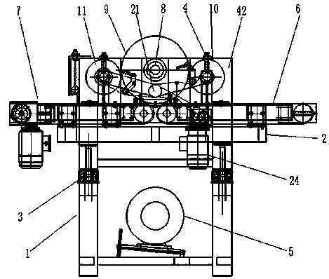
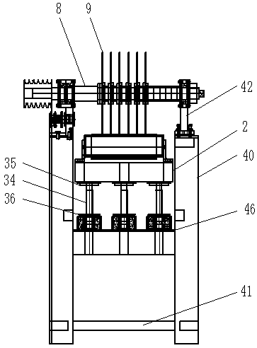
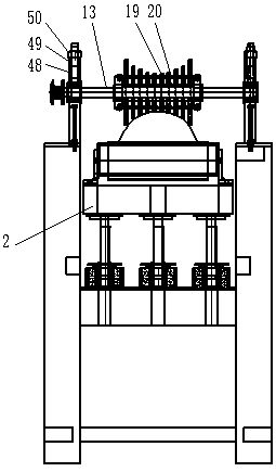
[0033] A woodworking machine tool, comprising a frame 1, a workbench 2, a wood conveying mechanism, a workbench lifting mechanism 3, a sawing mechanism, a sawing transmission mechanism, a pressure roller mechanism, a pressure material adjustment mechanism 4, and a pressure roller transmission mechanism. The sawing transmission mechanism includes a sawing transmission motor 5, and the sawing mechanism includes a sawing shaft 8. It is characterized in that: the workbench 2 is provided with a feeding conveying mechanism 6 and a discharging conveying mechanism 7 sequentially from front to back, A sawing shaft 8 is arranged above the middle of the feeding conveying mechanism 6 and the discharging conveying mechanism 7, and saw blades 9 are arranged at intervals on the sawing shaft 8, and the lowest point of the lower end of the saw blades 9 is located at the feeding conveying mechanism 6 It is in the middle of the material delivery mechanism 7 and lower than the upper end surface of...

Embodiment 2

[0042] A woodworking machine tool, comprising a frame 1, a workbench 2, a wood conveying mechanism, a workbench lifting mechanism 3, a sawing mechanism, a sawing transmission mechanism, a pressure roller mechanism, a pressure material adjustment mechanism 4, and a pressure roller transmission mechanism. The sawing transmission mechanism includes a sawing transmission motor 5, and the sawing mechanism includes a sawing shaft 8. It is characterized in that: the workbench 2 is provided with a feeding conveying mechanism 6 and a discharging conveying mechanism 7 sequentially from front to back, A sawing shaft 8 is arranged above the middle of the feeding conveying mechanism 6 and the discharging conveying mechanism 7, and saw blades 9 are arranged at intervals on the sawing shaft 8, and the lowest point of the lower end of the saw blades 9 is located at the feeding conveying mechanism 6 It is in the middle of the material delivery mechanism 7 and lower than the upper end surface of...


PUM


Abstract

The invention relates to the technical field of woodworking machinery, in particular to a woodworking machine tool which comprises a rack, a working table, a wood conveying mechanism, a working tablelifting mechanism, a saw-cutting mechanism, a saw-cutting transmission mechanism, a pressure roller mechanism, a pressing and adjusting mechanism and a pressure roller transmission mechanism. A feeding conveyor and a discharging conveyor are arranged on the working table; a saw-cutting shaft is arranged above the middle between the feeding conveyor and the discharging conveyor; saw blades are arranged on the saw-cutting shaft at intervals; pressing columns are arranged on a discharging pressure roller or a feeding pressure roller at intervals; the lengths of the pressing columns are graduallyincreased from the middle of the discharging pressure roller or the feeding pressure roller; the discharging pressure roller and the feeding pressure roller are connected through a chain, a chain wheel and an output chain wheel on a pressure roller drive motor; and a lifting mechanism is arranged under the working table. The woodworking machine tool provided by the invention is low in production cost, high in levelling efficiency, free of damaging a conveyor belt, and capable of effectively limiting and saw-cutting woods with arched upper end surfaces, different axial heights and irregular radial arched surfaces.

Description

technical field [0001] The invention relates to the technical field of woodworking machinery, in particular to a woodworking machine tool. Background technique [0002] As everyone knows, the existing woodworking planer is composed of a body, a workbench, a movable workbench, a left side plate, a right side plate, an upper planer shaft, a lower planer shaft, a lower planer shaft motor, a transmission device, a workbench lifting device, a Material pressure roller, discharge pressure roller, planer bearing seat, pressure roller bearing seat, pressure roller bearing seat, pressure adjustment device, upper pressure plate and protective cover, the transmission device includes the feed pressure roller gear, the discharge pressure roller gear , tensioning chain, variable speed gear set, tensioning lever, tensioning wheel, tension spring, upper planer shaft motor and upper planer shaft drive wheel, the center of the lower end of the worktable is fixedly connected with the machine bo...

Claims


Application Information

Patent Timeline
Patent Type & Authority Applications(China)
IPC IPC(8): B27B5/22B27B5/29B27B27/00B27B31/00
CPCB27B5/22B27B5/29B27B27/00B27B31/006
Inventor 王炳南
Owner 王炳南
Why Eureka
Try Eureka