Eureka AIR delivers breakthrough ideas for toughest innovation challenges, trusted by R&D personnel around the world.

Diamond resin wheel and mold and method for machining resin wheel

A resin grinding wheel and diamond technology, which is applied in the field of grinding and processing, can solve problems such as inconvenience in use and production, and achieve the effects of reducing processing strength, improving machine tool application rate, and reducing internal space.

Active Publication Date: 2018-10-30
湖南鑫星凌金刚石工具有限公司
View PDF4 Cites 3 Cited by
  • Summary
  • Abstract
  • Description
  • Claims
  • Application Information

AI Technical Summary

Problems solved by technology

However, most of the existing grinding wheels are single-process grinding wheels, that is, in the grinding operation, different grinding wheels must be replaced according to the rough grinding, semi-finishing or fine grinding process. Therefore, the processing and production of grinding wheels are also processed and produced separately. bring a lot of inconvenience
And most of the existing grinding wheels adopt the structure combined with the base and the abrasive layer. How to make the base and the abrasive layer effectively bond during the processing and production of the grinding wheel can simplify the processing flow and improve the production efficiency of the grinding wheel, especially the multi-abrasive layer grinding wheel.

Method used


Image

  • Diamond resin wheel and mold and method for machining resin wheel
  • Diamond resin wheel and mold and method for machining resin wheel
  • Diamond resin wheel and mold and method for machining resin wheel

Examples


Embodiment 1

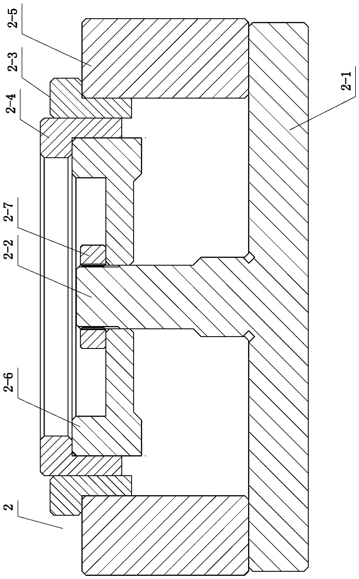
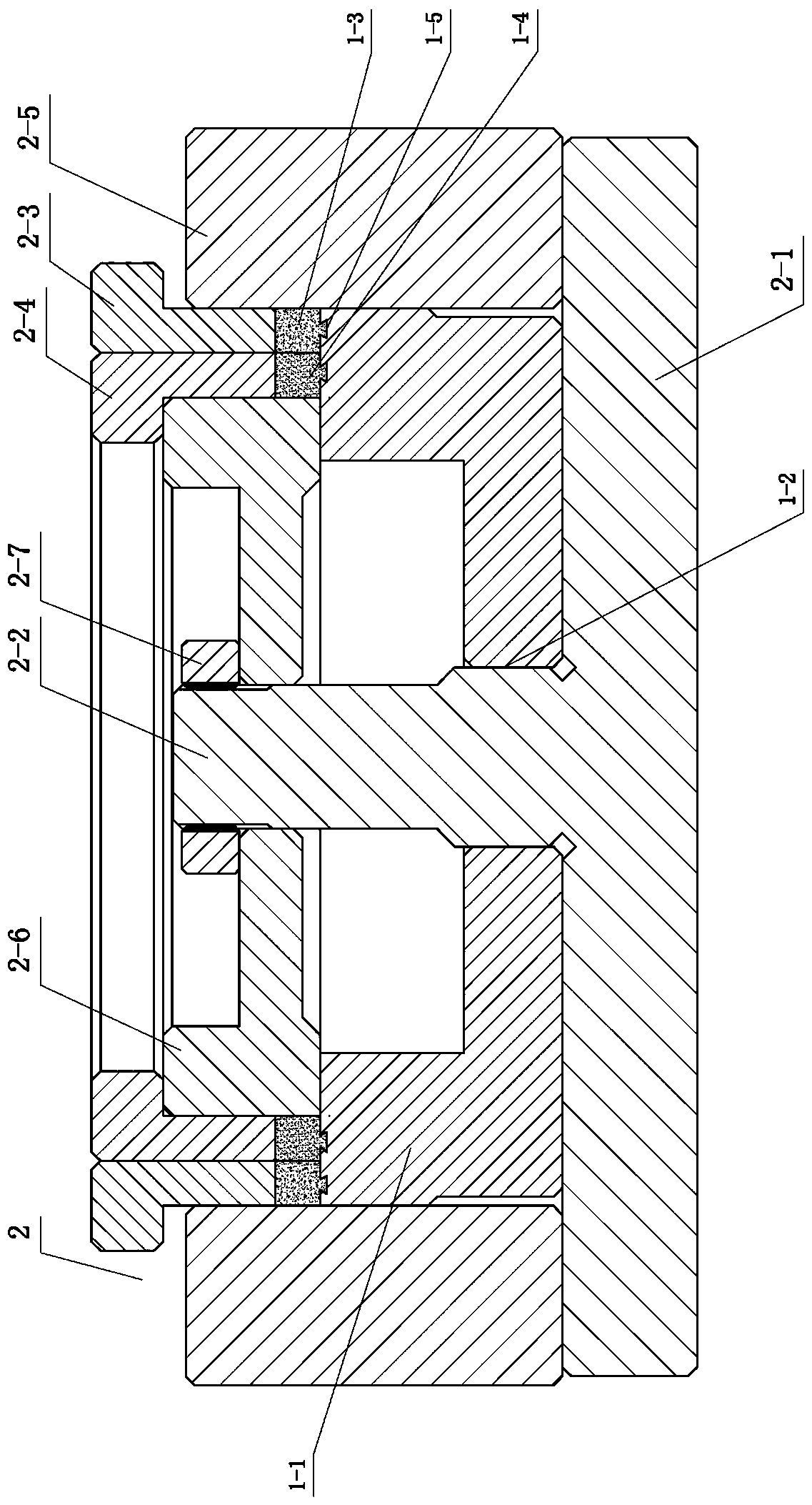
[0042] Such as figure 1 , 2 As shown, the processing mold 2 of the emery wheel of the present invention includes a positioning base 2-1 with a protruding assembly rod 2-2 in the middle, a mold frame 2-5 arranged on the positioning base 2-1, and a mold frame 2-5 sleeved on the assembly rod 2-2. Center die 2-6 on 2. Wherein: the inner wall of the mold frame 2-5 and the bottom surface of the central mold 2-6 form a placement area for the diamond resin grinding wheel substrate 1-1. There is a gap between the inner wall of the mold frame 2-5 and the outer wall of the central mold 2-6, and a coarse abrasive laminating head 2-3 and a fine abrasive laminating head 2-4 are arranged in the gap, and the coarse abrasive laminating head 2-3 is sleeved outside the fine abrasive laminating head 2-4, and can realize the pressing and forming of the coarse-grained abrasive layer 1-3 and the fine-grained abrasive layer 1-4 on the diamond resin grinding wheel substrate 1-1.

[0043] More speci...

Embodiment 2

[0060] Such as Figure 7 As shown, the mould, method and grinding wheel structure used in this embodiment are basically the same as those in Embodiment 1, the main difference is that the fine-grained abrasive layer 4 and the coarse-grained abrasive layer 3 are arranged on the outer circle of the base 1 from the inside to the outside. The fine-grained abrasive layer 4 is bonded to the substrate 1 using a dovetail structure, and the coarse-grained abrasive layer 3 is bonded to the outer circle of the fine-grained abrasive layer 4 . During processing, it is only necessary to move the gap between the coarse abrasive lamination head, the fine abrasive lamination head and the corresponding outer wall of the central mold and the inner wall of the mold frame to the position of the outer circle of the base body 1, first press the inner layer of fine-grained abrasive layer 4, and then Press the outer coarse-grained abrasive layer 3, and the others are all the same as the example 1 metho...

Embodiment 3

[0062] Such as Figure 8 As shown, the present embodiment is basically the same as the embodiment 2, except that the coarse-grained abrasive layer 3 and the fine-grained abrasive layer 4 are superimposed on the outer circle of the substrate 1 . The two abrasive layers are bonded to the substrate 1 respectively using a dovetail structure. During processing, it is only necessary to move the gap between the coarse abrasive laminating head, the fine abrasive laminating head and the corresponding outer wall of the central mold and the inner wall of the mold frame to the outer circle of the base body 1, firstly press the lower fine-grained abrasive layer 4, and then press Upper floor coarse-grained abrasive material layer 3, other are all identical with example 1 method.


PUM


Abstract

The invention relates to a diamond resin wheel and a mold and a method for machining the resin wheel. The resin wheel comprises a base body and abrasive material layers, wherein the abrasive layers are at least two abrasive layers which are fixed on the surface or the outer circle of a base body through extrusion and hot pressing, and each abrasive layer is formed by mixing and pressing differentcoarse and thin diamond particles and a binding agent; and the bonding position of the abrasive material layers and the base body are adopted with a dovetail-type structure, and the bonding faces arefurther processed into rough surfaces; the mold comprises a positioning base, a mold frame and a center mold, wherein the inner wall of the mold frame and the bottom face of the center mold form a placement area of the diamond resin wheel base body, a gap for installing a pressure head is arranged between the inner wall of the mold frame and the outer wall of the center mold, and the center mold is assembled with an assembling rod in a fixed mode through a fastening nut to be limited; the method for machining the resin wheel comprises the following steps that 1) the resin wheel base body is prepared; 2) the base body is fixed; 3) the abrasive material layers are pressed in advance; 4) hot-pressing forming is carried out; and 5) shaping and manufacturing are carried out. According to the method, a specially designed mold and a machining mode are adopted, so that the resin wheel with multiple utilization can be produced, and the grinding efficiency is improved.

Description

technical field [0001] The invention relates to the technical field of grinding, in particular to a diamond resin grinding wheel, a mold and a method for processing the grinding wheel. Background technique [0002] Grinding wheel is the most important type of abrasive tool in grinding process. The grinding wheel is a porous body made by adding a binder to the abrasive, compacting, drying and firing. Grinding wheel is the most widely used type of grinding tool. It rotates at high speed when used, and can be used for rough grinding, semi-finishing and Fine grinding as well as grooving and parting off etc. But at present, in the grinding operation, rough grinding, semi-finishing and fine grinding need to be processed by multiple processes respectively, and different grinding wheels need to be replaced according to the needs of grinding, which leads to a high occupation rate of equipment resources and low work efficiency. [0003] At present, mold molding is used when process...

Claims


Application Information

Patent Timeline
IPC IPC(8): B24D7/14B24D18/00
CPCB24D7/14B24D18/0009
Inventor 郑智钊
Owner 湖南鑫星凌金刚石工具有限公司
Why Eureka
Eureka Blog
Learn More