
Adjusting circuit for constant voltage output of switching power supply

A constant voltage output, switching power supply technology, applied in the direction of regulating electrical variables, output power conversion devices, control/regulation systems, etc., can solve the problems of poor EMI characteristics of switching power supplies, narrow energy spectrum, increasing the size and cost of switching power supplies, etc.

Active Publication Date: 2019-11-12
SUZHOU POWERON IC DESIGN
View PDF6 Cites 0 Cited by
  • Summary
  • Abstract
  • Description
  • Claims
  • Application Information

AI Technical Summary

Problems solved by technology

[0003] Traditional switching power supply constant voltage output adjustment circuit and method, when the AC input voltage is low and / or working in continuous current mode (CCM), the center value of the output voltage has the same frequency as the AC frequency fluctuations, and then presents the output voltage The characteristic of large ripple cannot meet the design requirements of most power supply applications. In order to suppress the output voltage ripple, a large input capacitor C is required BULK , which will greatly increase the size and cost of the switching power supply
[0004] In addition, for stability considerations, when working in continuous current mode (CCM), the power switch is generally switched at a fixed frequency, and for conversion efficiency considerations, when working in discontinuous current mode (DCM), the drain of the power switch MOS is generally Source-to-source voltage V DS The valley is turned on (valley conduction mode or QR mode), the energy spectrum is narrow in the two operating modes, the EMI characteristics of the switching power supply are poor, or the peripheral components of the integrated circuit are required to improve the EMI characteristics, which also increases the volume and cost of the switching power supply

Method used


Image

  • Adjusting circuit for constant voltage output of switching power supply
  • Adjusting circuit for constant voltage output of switching power supply
  • Adjusting circuit for constant voltage output of switching power supply

Examples


Embodiment Construction

[0041] In order to have a clearer understanding of the technical features, purposes and effects of the present invention, specific implementations are now described in detail.

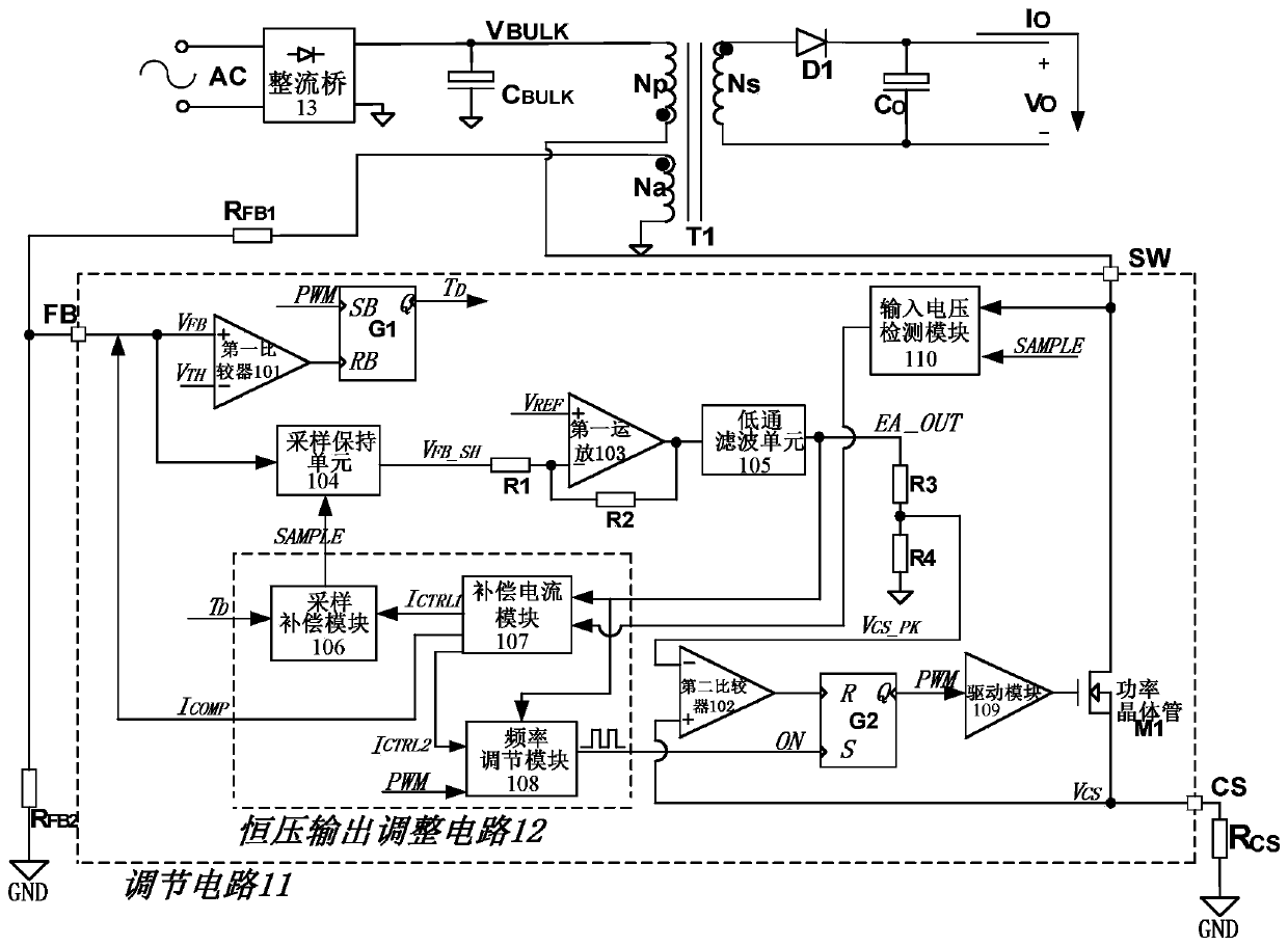
[0042] The adjustment circuit of the constant voltage output of the switching power supply is applied to the power system, such as figure 1 As shown, including rectifier bridge, capacitor C BULK , transformer T1, diode D1, capacitor C O , resistance R FB1 , resistance R FB2 , resistance R CS And the regulating circuit, the input terminal of the rectifier bridge is connected with the AC input terminal AC; the output terminal of the rectifier bridge is connected with the primary side N of the transformer T1 p The first terminal of the capacitor C BULK connected; the second end of the primary side of the transformer T1 is connected to the SW pin of the regulating circuit 11; the auxiliary side N of the transformer T1 a with resistor R FB1 The first end is connected; the resistor R FB1 The second t...


PUM


Abstract

The invention relates to an adjusting circuit for switching power supply constant voltage output, and the adjusting circuit comprises a first comparator, a first RS latch, a sampling and holding unit,a first resistor, a second resistor, a third resistor, a fourth resistor, a first operation amplifier and low-pass filtering unit, a second comparator, a second RS latch, a driving module, a power transistor and a constant voltage output adjusting circuit, wherein the constant voltage output adjusting circuit comprises a current compensating module, a frequency adjusting module and a sampling compensation module. When alternating current input voltage is relatively low and output power is relatively high and / or a switching power supply works in a continuous current mode, switching frequency and / or sampling moment of voltage on an output voltage feedback management pin and / or the voltage on the output voltage feedback pin are adjusted to vary with variation of the voltage on input capacitance, ripple wave generated by the output voltage varying with variation of the voltage on the input capacitance is restrained, variation of the switching frequency is adjusted, and switching frequencyspectrum is expanded.

Description

technical field [0001] The invention relates to an adjustment circuit for constant voltage output of a switching power supply, which is suitable for power management integrated circuits and belongs to the technical field of power semiconductors. Background technique [0002] The flyback switching power supply used in AC-DC conversion generally uses a rectifier bridge after the AC input to convert the AC input into a relatively DC voltage and store it in an input capacitor. The capacitance of the input capacitor determines the The fluctuation range of the storage voltage (especially when the effective value of the input AC voltage is low), for example: the larger the capacitance value, the smaller the fluctuation range. On the other hand, in consideration of the design cost of the power supply, the capacitance value of the capacitor is related to the output power applied by the power supply, for example, when the output power is high, a larger input capacitance value is selec...

Claims


Application Information

Patent Timeline
Patent Type & Authority Patents(China)
IPC IPC(8): H02M3/335
CPCH02M3/33523
Inventor 刘文亮李海松赵倡申易扬波
Owner SUZHOU POWERON IC DESIGN
Learn More