Riboflavin promoting low concentration CO2 electrochemical trapping method

A low-concentration, electrochemical technology, applied in chemical instruments and methods, inorganic chemistry, electrolysis process, etc., can solve the problems of high energy consumption and high capture cost, reduce energy consumption, improve economic feasibility, and reduce capture cost Effect

Active Publication Date: 2018-11-02
SICHUAN UNIV
View PDF2 Cites 12 Cited by
  • Summary
  • Abstract
  • Description
  • Claims
  • Application Information

AI Technical Summary

Problems solved by technology

However, CO 2 The cost of capture accounts for about 2 75% of the total cost of abatement is constrained CO 2 Main reasons for the economic viability of emission reduction
[0003] while CO 2 The main reason for the high cost of capture is due to excessive energy consumption, so the development of efficient and energy-saving carbon capture methods is very important for reducing CO 2 Reducing emissions and energy consumption is crucial

Method used


Image

  • Riboflavin promoting low concentration CO2 electrochemical trapping method
  • Riboflavin promoting low concentration CO2 electrochemical trapping method
  • Riboflavin promoting low concentration CO2 electrochemical trapping method

Examples


example 1

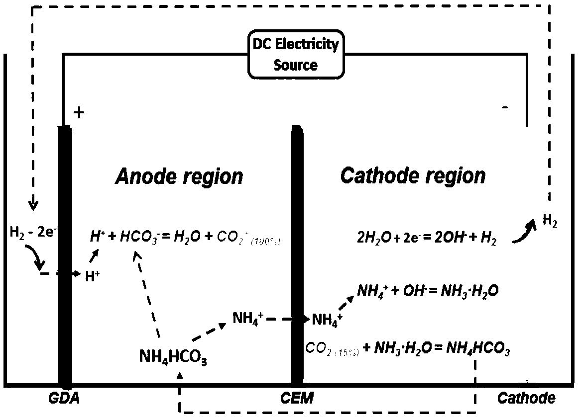
[0060] This example FMN / FMNH 2 Redox pair promotes low CO concentration 2 The principle of electrochemical trapping is as Figure 4 shown.

[0061] in as CO 2 In the shell container of electrochemical collection, a cation exchange membrane that only allows cations to pass through and can prevent anions from passing through is separated into two regions, the anode area and the cathode area.

[0062] Anolyte (1M NaHCO 3 +0.08M FMNH 2 ) and catholyte (1M NaHCO 3 +0.08M FMN) is placed in a 200mL airtight storage tank, and the flow rate of 15mL / min is circulated between the electrolyzer device and the storage tank through a pump, and graphite felt is used as the electrode material, and a DC power supply is applied between the positive and negative electrodes (IT6932A, Itech) power supply, the temperature of the electrolytic cell is 50 ℃.

[0063] Under the action of current, FMN gets two electrons at the cathode, from KHCO 3 The solution receives two protons to form reduced...

example 2

[0070] in as CO 2 In the shell container of electrochemical collection, a cation exchange membrane that only allows cations to pass through and can prevent anions from passing through is separated into two regions, the anode area and the cathode area.

[0071] Anolyte (0.3M NaHCO 3 +0.06M FMNH 2 ) and catholyte (0.3M NaHCO 3 +0.06M FMN) placed in a 200mL airtight storage tank, circulated at a flow rate of 15mL / min between the electrolyzer device and the storage tank through a pump, and 10mL / min of 12% CO was introduced into the cathode area 2 CO 2 / N 2 mixed composition. Graphite felt was used as the electrode material, a DC power supply (IT6932A, Itech) was applied between the cathode and anode electrodes, and the temperature of the electrolytic cell was 55°C.

[0072] When the current density is maintained at 50mA cm -2 When the average voltage is 0.075V, than 10mA cm -2 The 0.065V at the time has increased by 15.3%. From this calculation, every ton of CO captured 2...


PUM


Abstract

The invention provides a riboflavin promoting low concentration CO2 electrochemical trapping method, and belongs to the technical field of CO2 electrochemical trapping. The method comprises the following steps that a cation-exchange membrane is placed in an electrolytic cell; a FMN solution and a potassium acid carbonate solution are added in acathode zone; a FMNH2 solution and a potassium acid carbonate solution are added in an anode zone; direct current is applied between the anode electrode and the cathode electrode; two electrons are obtained in the cathode electrode by the FMN; two protons are received in a KHCO3 solution to form the FMNH2 solution in the reduction state; generated CO32-enters the solution and is used for absorbing low concentration CO2; the FMNH2 releases electrons at the anode electrode and returns to a oxidized state FMN; and the protons leave the FMNH2 to react with KHCO3 in the solution to release high concentration CO2. Low concentration CO2 trapping is achieved; when electric current density is at 10mAcm-2, the average voltage for trapping the CO2 is 0.065V, energy consumption of trapping one ton of the CO2 is about 80KWh, while energy consumption of trapping one ton of the CO2 by an existing chemical absorption method of MES regeneration is 370-510 KWh, so that energy saving is more than 75%.

Description

technical field [0001] The invention belongs to electrochemical capture CO 2 Technical field, specifically a kind of riboflavin promotes low concentration CO 2 method of electrochemical capture. Background technique [0002] Combustion of fossil fuels is the main source of carbon dioxide emissions, of which the emissions from large-scale industrial production processes such as thermal power plants and steel mills account for about 40% of the total carbon dioxide emissions. Among the currently feasible emission reduction options, such as CO 2 Geological storage, CO 2 For ocean storage, etc., it is necessary to first release low-concentration CO 2 to capture. However, CO 2 The cost of capture accounts for about 2 75% of the total cost of abatement is constrained CO 2 The main reasons for the economic viability of emission reductions. [0003] while CO 2 The main reason for the high cost of capture is due to excessive energy consumption, so the development of efficien...

Claims


Application Information

Patent Timeline
Patent Type & Authority Applications(China)
IPC IPC(8): C25B1/00C25B9/00C01B32/50
CPCC01B32/50C25B1/00C25B9/00
Inventor 王昱飞谢和平刘涛
Owner SICHUAN UNIV
Why Eureka
Try Eureka