
Carbon fiber honeycomb tube structure

A honeycomb tube and carbon fiber technology, applied in the design features of springs/shock absorbers, shock absorbers, springs, etc., can solve the problems of difficulty in achieving energy absorption, low specific energy absorption and specific strength, and cumbersome production steps, etc. Achieve the effect of light structure, low density and flexible preparation

Inactive Publication Date: 2018-11-02
NANJING UNIV OF AERONAUTICS & ASTRONAUTICS
View PDF6 Cites 5 Cited by
  • Summary
  • Abstract
  • Description
  • Claims
  • Application Information

AI Technical Summary

Problems solved by technology

When the above-mentioned materials are used as energy-absorbing structures, their specific energy absorption and specific strength are relatively low, and it is difficult to achieve the energy-absorbing effect required by the design. Moreover, these materials have a single form, and the manufacturing steps are cumbersome, and the obtained protective structures are often relatively heavy.

Method used


Image

  • Carbon fiber honeycomb tube structure
  • Carbon fiber honeycomb tube structure

Examples


Embodiment Construction

[0018] Below in conjunction with specific embodiment and accompanying drawing, technical scheme of the present invention is described further:

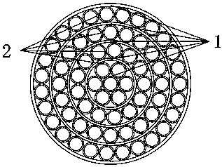
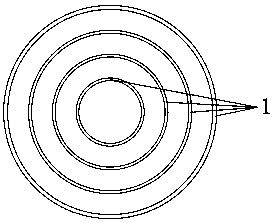
[0019] Such as figure 1 As shown, a carbon fiber honeycomb tube structure, including a large tube 1 and a small tube 2; the large tubes 1 are arranged in sequence from the inside to the outside, and there are N layers; each layer of large tubes 1 is arranged in parallel to form a concentric circle; the Nth layer of large tubes (1) Arranged on the outermost side of the honeycomb structure, the small tubes 2 are not filled in the large tubes 1 of the first layer, and the small tubes 2 are evenly filled between the large tubes 1 . 7N-8 identical small tubes 2 are evenly filled between the large tube 1 of the N-th layer and the large tube 1 of the N-1 layer; the outer diameter of the small tube 2 is equal to the inner diameter of the large tube 1 of the N-th layer minus the large tube of the N-1 layer 1 difference in outer diameter. Bot...


PUM


Abstract

The invention discloses a carbon fiber honeycomb tube structure, and relates to the field of protective structures. A traditional protective structure is high in weight and simplex in material and structure form. A carbon fiber honeycomb tube is prepared from pultrusion tubes with orthogonal carbon fibers being laid, and the large tubes and the small tubes are connected into a whole through resin.The carbon fiber tube structure obtained through a pultrusion process has the advantages of large strength, high stiffness, fast forming and the like, and is lower in weight, larger in stiffness andhigher in specific energy absorption compared with the traditional protective structure; and the needed forms can be prepared according to the demands, and the application range is wide.

Description

technical field [0001] The invention relates to the field of protective structures, in particular to a carbon fiber honeycomb pipe structure. Background technique [0002] In the field of protective structures, in the face of high-speed collision objects, the energy absorption characteristics of the protective structure play a crucial role in the effectiveness of its structure. Whether it can rely on various failure modes such as buckling, damage, and fracture of its own structure to reduce the impact load during high-speed collisions and dissipate impact energy is a matter of great concern in the field of protective structures and other fields. For example, the anti-missile penetration process of the target body; the soft landing process of the last stage buffer energy-absorbing device of the aerospace vehicle; the landing process of the landing gear device when the aircraft lands; the landing process of the airdrop system equipment for military equipment; the guardrail on ...

Claims


Application Information

Patent Timeline
Patent Type & Authority Applications(China)
IPC IPC(8): F16F7/00
CPCF16F7/003F16F2224/02F16F2230/0023
Inventor 范华林李万欣
Owner NANJING UNIV OF AERONAUTICS & ASTRONAUTICS
Learn More