Minimally invasive bone taking equipment

A device and bone tissue technology, applied in the field of medical devices, can solve the problems of easy to leave sequelae, inconvenient bone removal, patient injury, etc., to reduce the risk of lateral femoral cutaneous nerve injury, rapid operation, and less trauma.

Pending Publication Date: 2018-11-06
ZHEJIANG FRIEND MEDICAL TECH CO LTD
View PDF0 Cites 6 Cited by
  • Summary
  • Abstract
  • Description
  • Claims
  • Application Information

AI Technical Summary

Problems solved by technology

[0005] In order to overcome the deficiencies of the prior art, the present invention solves the technical problems that the original bone extraction method has a large incision, inconvenient bone extraction, and is easy to cause injury to the patient and leave sequelae, and provides a minimally invasive bone extraction device, which only A small skin incision and a small bo

Method used


Image

  • Minimally invasive bone taking equipment
  • Minimally invasive bone taking equipment
  • Minimally invasive bone taking equipment

Examples


Embodiment 1

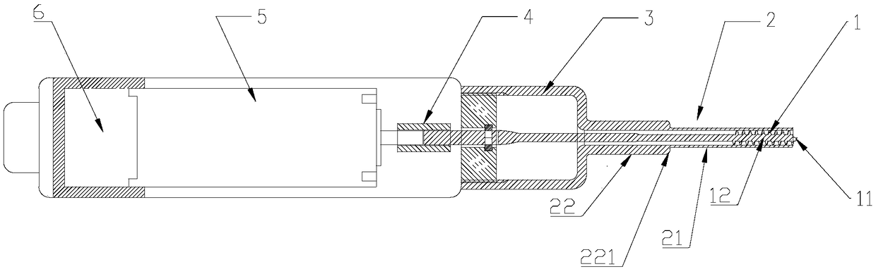
[0070] figure 1 It is a structural schematic diagram of a minimally invasive bone harvesting device in an embodiment of the present invention. Such as figure 1 As shown, the minimally invasive bone harvesting device of the present invention includes a cutter 1 , a sleeve 2 , a material collection device 3 and a drive control system 5 .

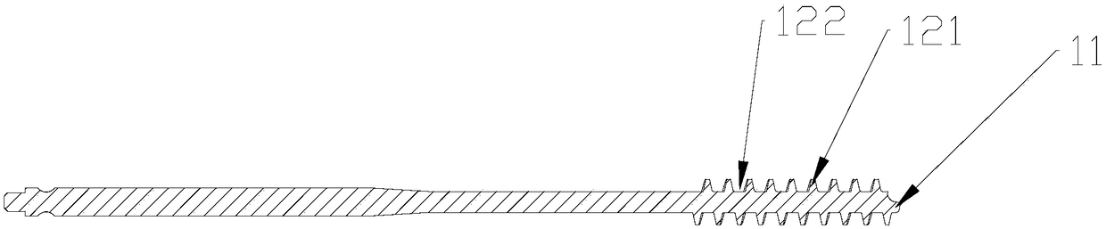
[0071] figure 2 It is a schematic diagram of the cutter structure of the minimally invasive bone harvesting device in another embodiment of the present invention. Such as figure 2 As shown, the cutter 1 includes a cutter head 11 and a screw conveying part 12 .

[0072] The cutter head 11 mainly plays the role of guiding the cutter to go deep into the bone tissue or cutting or grinding the bone tissue at the same time. The cutter head 11 can be a grinding head or a drill. The cutter head 11 can be a small-diameter blunt head without cutting edges, or can be provided with multiple cutting edges.

[0073] The shape and surface characteris...

Embodiment 2

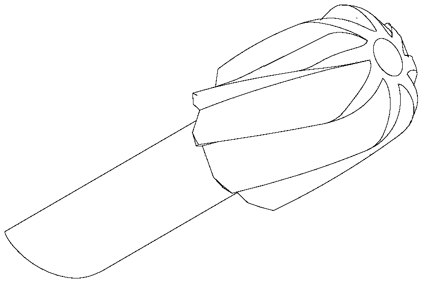
[0097] image 3 It is a schematic diagram of the cutter head structure of the cutter in Embodiment 2 of the present invention. The cutter head 11 is provided with a plurality of helical blades, and each helical blade does not reach the center of the end surface of the cutter head 11 . That is, the center of the end of the cutter head 11 is a blunt surface without sharpening. This point is an important invention point of the present invention, and the sharpening of the cutter head does not open to the center of the end of the cutter head 11, so that it can be ensured that the ends of the cutter head 11 are all provided with a blunt surface of a certain size, so that the cutter can be used during the operation. It has the function of protecting cortical bone from being penetrated.

[0098] The front ends of the helical blades of the cutter head 11 are all acute angles. The present invention is aimed at the characteristics of autologous bone transplantation, and the cutter hea...

Embodiment 3

[0100] Figure 4 It is a schematic diagram of the cutter head structure of the cutter of the minimally invasive bone harvesting device in Example 3 of the present invention. Such as Figure 4 As shown, the shape of the cutter head in this embodiment is spherical, and the cutter head is provided with a plurality of helical blades, the helical blades are oblique blades, and each helical blade does not reach the center of the end face of the cutter head.


PUM


Abstract

The invention provides minimally invasive bone taking equipment. The minimally invasive bone taking equipment is provided with a bone taking structure and a spiral conveying part and is characterizedin that the bone taking structure is used for taking down bone tissue, and the thread of the spiral conveying part is used for conveying the taken down bone tissue. The minimally invasive bone takingequipment has the advantages that the equipment only needs a tiny skin cut and a tiny bone window, cancellous bone is cut or ground into skeletal fragments or cancellous bone particles and then conveyed through threaded channels, oriented conveying of the cut or ground cancellous bone is achieved, operation convenience and quickness are achieved, hurt, caused by bone cutting surgery, to a patientis lowered greatly, sequelae are reduced, and surgery safety is increased.

Description

technical field [0001] The invention relates to a medical device, in particular to a minimally invasive bone tissue operation equipment, which is used for performing cutting (grinding) operation on bone tissue and directional transmission of the cut (grinded) cancellous bone particles. Background technique [0002] Bone grafting is to transplant bone tissue to the bone defect in the patient's body that needs to be strengthened or fused through surgery. It is commonly used in the field of orthopedics such as bone defect, nonunion of fracture, bone disease or cavity filling after bone tumor curettage, spine and joints. Fusion, etc., as well as bone grafting in oral surgery, dental implantology, plastic surgery, and neurosurgery. [0003] The commonly used autologous bone graft has many advantages, such as good histocompatibility, no graft rejection, strong osteoinductive effect, etc., and has a good effect of promoting bone fusion. Commonly used bone harvesting sites for auto...

Claims


Application Information

Patent Timeline
IPC IPC(8): A61B17/16
CPCA61B17/1617A61B17/1628A61B17/1635A61B17/1659
Inventor 肖杰
Owner ZHEJIANG FRIEND MEDICAL TECH CO LTD
Why Eureka
Try Eureka