
Carbon dioxide capture-photocatalysis coupling reaction apparatus and application method thereof

A carbon dioxide, coupled reaction technology, applied in chemical instruments and methods, separation methods, gas treatment and other directions, can solve the problems of increasing production costs, cumbersome process flow, increased production costs, etc., to reduce production and equipment costs, shorten the process flow. , the effect of reducing energy waste

Active Publication Date: 2018-11-06
XIAN UNIV OF SCI & TECH
View PDF15 Cites 3 Cited by
  • Summary
  • Abstract
  • Description
  • Claims
  • Application Information

AI Technical Summary

Problems solved by technology

[0005] The above method has the following disadvantages: (1) The capture of carbon dioxide is carried out separately from the photocatalysis, resulting in cumbersome process flow and increased production costs; at the same time, the storage of carbon dioxide after capture also further increases the production cost; (2 ) Carbon dioxide must be collected through the adsorption-desorption process in the capture process, and then the collected carbon dioxide is photocatalytically converted, and in the process of photocatalytic conversion of carbon dioxide, carbon dioxide must be adsorbed around the catalytic site, so not only in the process The desorption of carbon dioxide causes a waste of energy

Method used


Image

  • Carbon dioxide capture-photocatalysis coupling reaction apparatus and application method thereof
  • Carbon dioxide capture-photocatalysis coupling reaction apparatus and application method thereof
  • Carbon dioxide capture-photocatalysis coupling reaction apparatus and application method thereof

Examples


Embodiment 1

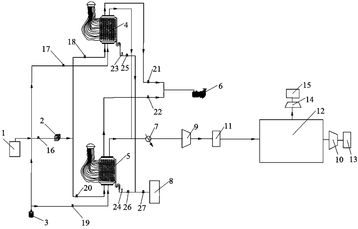
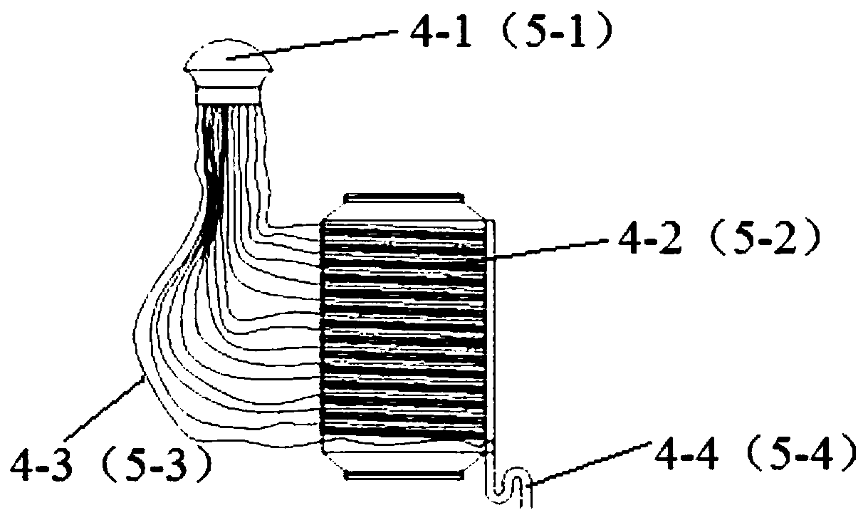
[0045] like figure 1 , figure 2 and image 3 As shown, the carbon dioxide capture-photocatalytic coupling reaction device of this embodiment includes a first reactor 4 and a second reactor 5 with the same structure, and provides the first reactor 4 and the second reactor 5 with CO 2 The gas storage tank 1 of the exhaust gas, and the gas separator 12 that is all connected with the outlet pipeline of the first reactor 4 and the second reactor 5, in the first reactor 4, there are a plurality of parallel arrangements along the vertical direction The first photocatalyst plate 4-2, the first optical fiber 4-3 is uniformly distributed between the adjacent first photocatalyst plates 4-2, and the first optical fiber 4-3 passes from the first reactor 4 extend out from the center and be connected and fixed with the first light source introducer 4-1, a plurality of second photocatalyst plates 5-2 are arranged in parallel in the vertical direction in the second reactor 5, and the adjace...

Embodiment 2

[0051] The method for using the carbon dioxide capture-photocatalytic coupled reaction device of this embodiment includes the following steps:

[0052] Step 1, immerse the activated carbon plate 29 in the slurry of the photocatalyst 28 to make the two fully contact, after the positive and negative sides of the activated carbon plate 29 are completely coated with the slurry of the photocatalyst 28, take it out and dry it to obtain the first photocatalyst plate 4-2 and the second photocatalyst plate 5-2, then a plurality of first photocatalyst plates 4-2 and a plurality of second photocatalyst plates 5-2 are loaded into the first reactor 4 and the second reactor 5 respectively middle;

[0053] Step 2: Turn on the vacuum pump 6 and open the sixth valve 21 and the seventh valve 22 to vacuumize the first reactor 4 and the second reactor 5, and close the vacuum pump 6, the sixth valve 21 and the seventh valve after the vacuuming is completed 22, then open the third valve 18 to make...


PUM


Abstract

The invention discloses a carbon dioxide capture-photocatalysis coupling reaction apparatus. The carbon dioxide capture-photocatalysis coupling reaction apparatus comprises two reactors having a samestructure, a gas storage tank for providing exhaust gas for two reactors, and a gas separator connected with two reactors, several photocatalyst plates are uniformly distributed in two reactors, optical fibers are distributed between adjacent photocatalyst plates, the optical fibers are stretched from the reactors and connected with a light source introduction device, the photocatalyst plates arethe active carbon plates with the surfaces coated with a photocatalyst, gas flow meters are arranged between the reactors and the gas storage tank, the reactor is connected with a water vapor generator, a vacuum pump and a cooler, a first compressor and a first storage tank are arranged between the cooler and the gas separator, and a second compressor and a second storage tank are arranged at an outlet of the gas separator. The invention also discloses an application method of the apparatus. The photocatalyst plate in the apparatus absorbs the CO2 and performs in-situ photocatalysis, the photocatalysis rate is increased, and the application method of the apparatus is simple and easy to control.

Description

technical field [0001] The invention belongs to the field of energy technology, and in particular relates to a carbon dioxide capture-photocatalysis coupling reaction device and a use method thereof. Background technique [0002] The combustion of fossil fuels is the main cause of the greenhouse effect, and its emissions have been vigorously controlled by people. However, my country's status of taking coal as the main energy source will not change for a long period of time in the future. CO 2 The emissions are still relatively large, so the CO 2 The capture of CO has become the most effective CO 2 emission reduction methods. [0003] Currently, photocatalytic conversion is the most promising CO 2 Comprehensive utilization of technology. However, the existing CO 2 Among photocatalytic conversion technologies, CO 2 Capture and then use a catalyst to catalytically convert it, the process requires the use of a large number of process equipment, while capturing the CO 2 D...

Claims


Application Information

Patent Timeline
Patent Type & Authority Applications(China)
IPC IPC(8): B01D53/86B01D53/62
CPCB01D53/62B01D53/86B01D2255/802B01D2257/504Y02A50/20Y02C20/40
Inventor 周安宁董羿繁李瑞琪赵小玲张亚刚雷东强
Owner XIAN UNIV OF SCI & TECH
Learn More