Cutting tool wear measurement method based on vibration spectrum and neural network

A tool wear and neural network technology, applied in the direction of measuring/indicating equipment, manufacturing tools, metal processing machinery parts, etc., can solve the problems of low detection accuracy and complex detection system

Inactive Publication Date: 2018-11-06
HARBIN UNIV OF SCI & TECH
View PDF7 Cites 19 Cited by
  • Summary
  • Abstract
  • Description
  • Claims
  • Application Information

AI Technical Summary

Problems solved by technology

The above-mentioned invention judges tool wear through various signals, t

Method used


Image

  • Cutting tool wear measurement method based on vibration spectrum and neural network
  • Cutting tool wear measurement method based on vibration spectrum and neural network
  • Cutting tool wear measurement method based on vibration spectrum and neural network

Examples


Embodiment Construction

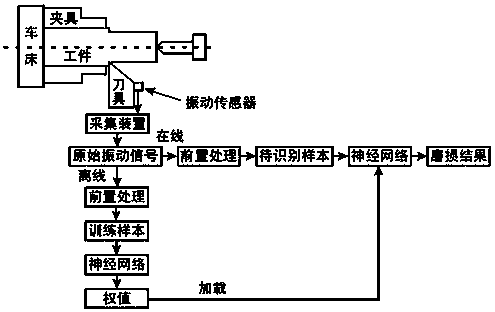
[0023] like figure 1 As shown, the tool wear detection method based on vibration spectrum and neural network of the present invention includes the following steps.

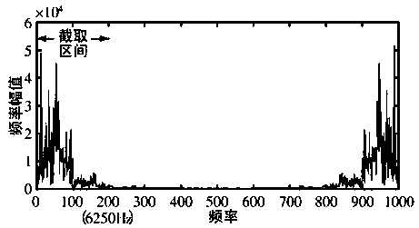
[0024] Step 001. Connect the vibration sensor to the tool handle of the turning tool near the tool head. The supporting equipment for the vibration sensor also includes a signal conditioner and a data acquisition card. The data acquisition card collects the original vibration signal and transmits the signal to the computer. The effective frequency band of the vibration signal during metal cutting generally does not exceed 8000Hz. When collecting the vibration signal, the collection frequency is set to 31250Hz to ensure the smooth collection of useful information.

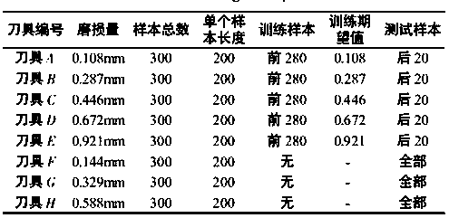
[0025] Step 002. Use the same 8 turning tools for actual cutting, and use the average value of the width of the wear zone in a certain range on the 1 / 2 of the flank as the tool bluntness standard, and obtain the wear amount of 0.108mm (A) and 0.287mm ( ...


PUM


Abstract

The invention provides a method for estimating cutting tool wear by vibration spectrum. The method comprises the steps: collecting a vibration signal in the cutting process by using a vibration sensor, and conducting Fourier transform for the vibration signal; inputting a vibration amplitude value of a spectrum concentration area into a neural network for training; establishing a mapping relationship between the vibration spectrum and cutting tool wear extent, and thus forecasting cutting tool wear.

Description

technical field [0001] The invention relates to a tool wear detection method based on vibration spectrum and neural network, belonging to the technical field of tool wear detection. Background technique [0002] Tool wear is an inevitable phenomenon in the process of processing. When the tool wears to a certain extent, the processing quality of the product will drop sharply. In severe cases, it will affect the normal operation of the processing system and even make the workpiece scrapped. In the traditional processing process, the staff often judge the wear degree of the tool roughly through the noise during cutting or the quality of the machined surface of the workpiece, but there are many interference factors in the judgment process, and it is related to the work experience of the staff. Often inaccurate. In order to ensure the processing quality of the product, it is imperative to detect the wear of the tool during the processing. [0003] In order to monitor the tool w...

Claims


Application Information

Patent Timeline
IPC IPC(8): B23Q17/09
Inventor 严复钢南月冲
Owner HARBIN UNIV OF SCI & TECH
Why Eureka
Try Eureka