Hub motor integrated system

An in-wheel motor and integrated system technology, applied in the direction of electromechanical devices, electrical components, electric components, etc., can solve the problems of not being suitable for heavy-duty vehicles, insufficient braking force, replacement of friction plates, etc., to achieve improved braking stability, braking Powerful, cost-saving effect

Inactive Publication Date: 2018-11-06
WUHAN UNIV OF TECH
View PDF7 Cites 3 Cited by
  • Summary
  • Abstract
  • Description
  • Claims
  • Application Information

AI Technical Summary

Problems solved by technology

[0004] Most of the existing wheel hub motor layout schemes are equipped with single tires, which are not suitable for the hub motor layout of dual tire drive vehicles. In addition, the existing hub electrical integration schemes are equipped with disc system The braking force of disc brakes is not large enough to be suitable for heavy-duty vehicles, and the cost of disc brakes is high and friction linings need to be replaced frequently

Method used


Image

  • Hub motor integrated system
  • Hub motor integrated system
  • Hub motor integrated system

Examples


Embodiment 1

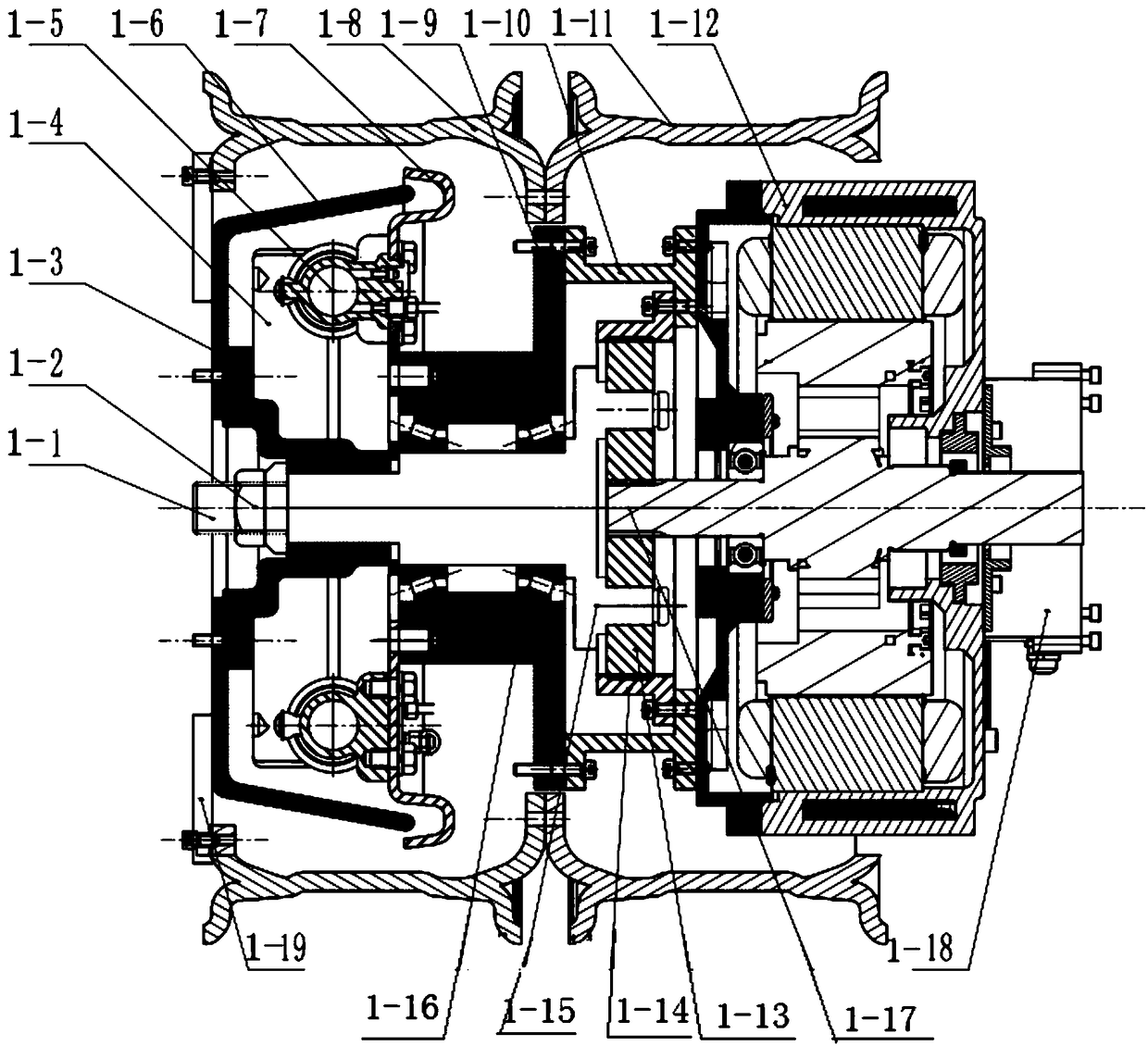
[0029] like figure 1 As shown, a hub motor integrated system is arranged in a double wheel, including a hub motor 1-12, a reducer and a brake, the hub motor 1-12 is arranged in the inner rim 1-11, and the reducer and brake are arranged on the outside In the rim 1-8, the reducer is a planetary gear reducer, and the hub motor output shaft 1-17 meshes with the planetary gear 1-13 of the reducer; the brake is a drum brake, including brake drum connectors 1-3, brake Shoe 1-4, brake wheel cylinder 1-5, brake drum 1-6 and brake base plate 1-7; the middle part of the brake drum connector 1-3 is socketed and fixed on the planetary gear output shaft of the reducer 1-1, the outside of the brake drum connector 1-3 is connected to the brake drum 1-6, the outside of the brake drum 1-6 is fixed to the spoke 1-19, and the inside of the brake drum passes through the brake base plate 1- 7 is connected to the brake support member 1-9; the brake wheel cylinder 1-5 is connected to the vehicle bra...

Embodiment 2

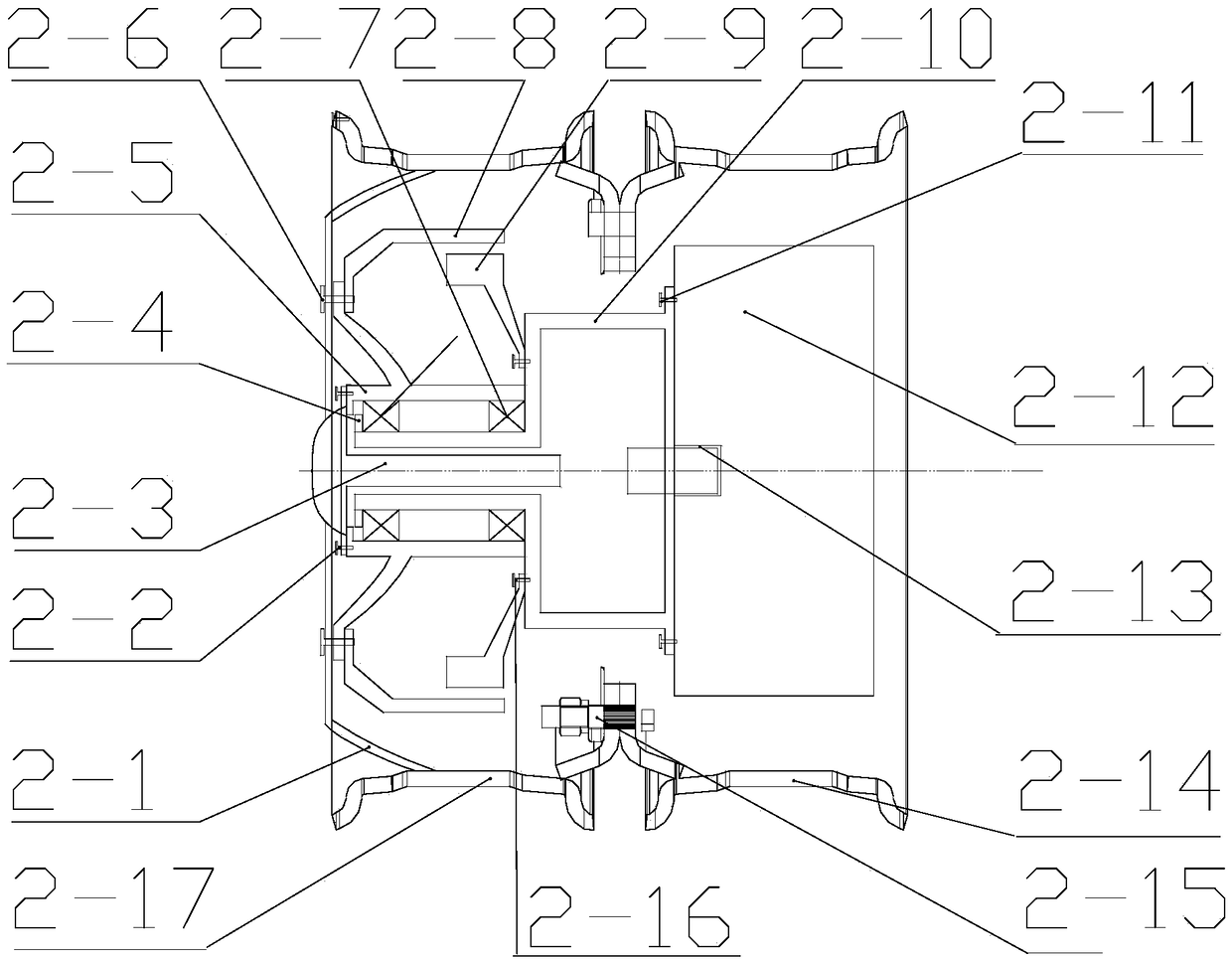
[0039] like figure 2 As shown, a dual wheel hub motor integrated system is arranged in a dual wheel, including a hub motor, a reducer and a brake. The hub motor is arranged in the inner rim 2-14, and the reducer and brake are arranged in the outer rim 2-14. In 17, the reducer is a planetary gear reducer, the output shaft of the hub motor meshes with the planetary gear of the reducer, and the planet carrier output shaft 2-3 of the reducer is connected to the hub 2-5; the inner rim 2-14 is connected to the outer rim 2- The two end faces of the rim spoke plate 2-1 of 17 are made into tapered surfaces, in order to be convenient to the bolt connection with brake. The inner rim 2-14 and the outer rim 2-17 are connected by bolts 2-15.

[0040] The brake is a drum brake, the brake base plate 2-9 of the drum brake is connected to the planetary gear reducer housing 2-10 through bolts 2-16, and the brake drum 2-8 of the drum brake is connected to the wheel hub 2-10. 5. The rim webs 2-...

Embodiment 3

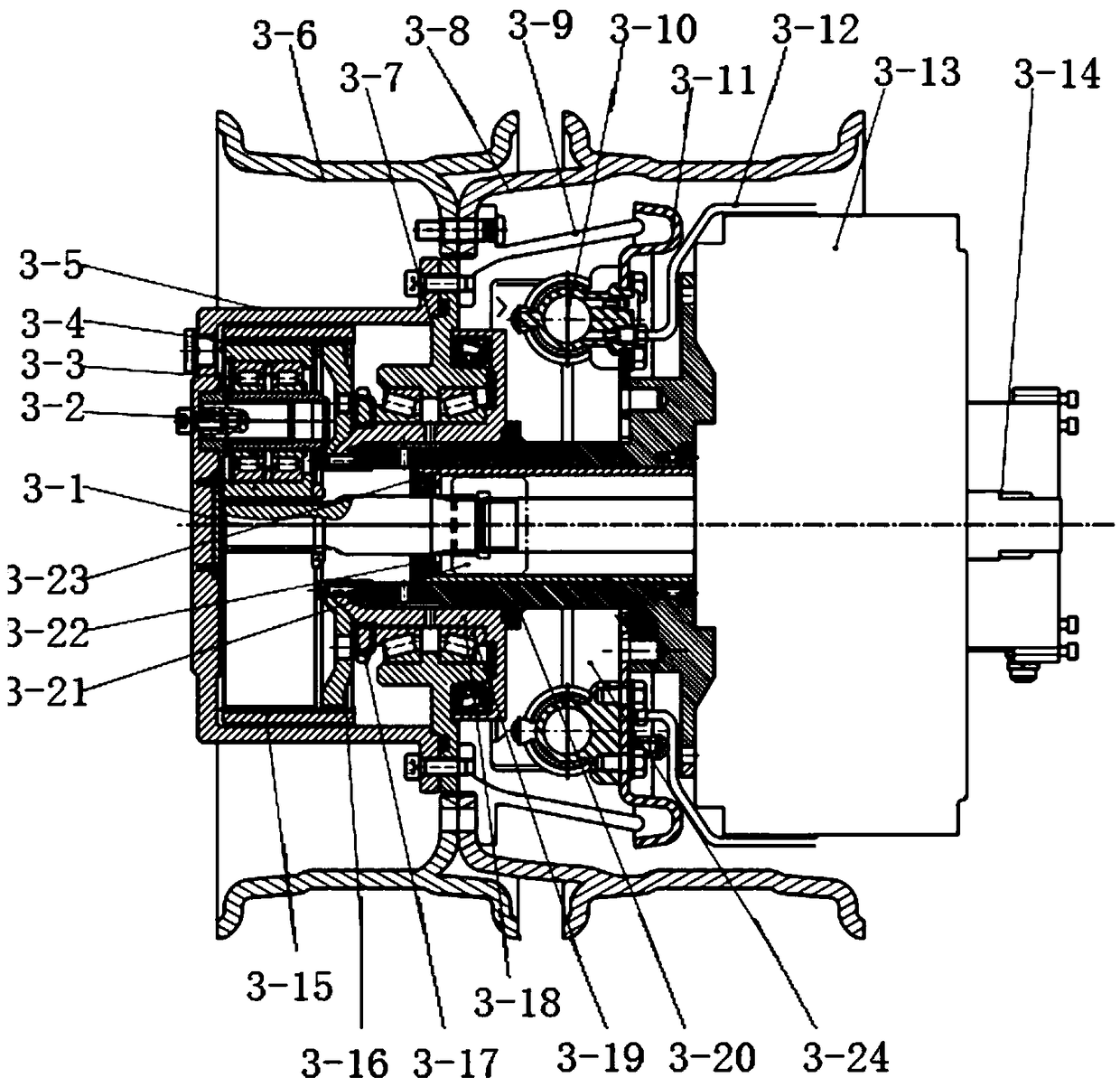
[0055] like image 3 As shown, a dual-type tire hub motor assembly is arranged in a dual-type wheel, including a hub motor 3-13, a reducer and a brake, the hub motor 3-13 is arranged in the inner rim 3-8, and the reducer is arranged on In the outer rim 3-6, the brake is set between the hub motor 3-13 and the reducer; the reducer is a planetary gear reducer, and the output shaft of the hub motor meshes with the sun gear 3-1 of the reducer through the coupling 21 to reduce the speed. The small planetary gear shaft 3-2 of the gear unit is connected with the output member 3-5 of the speed reducer.

[0056]The brake is a drum brake, and the drum brake includes a brake drum 3-9, a brake wheel cylinder 3-10, a brake shoe 3-24, a brake bottom plate 3-11 and a brake pipeline 3-12; Wherein the reducer output part 3-5 is connected with the left side of the brake drum 3-9, the top of the brake drum is connected with the spokes of the inner rim 3-8 and the outer rim 3-6, and the brake whe...


PUM


Abstract

The invention provides a hub motor integrated system which is arranged in a dual wheel. The system comprises a hub motor, a speed reducer and a brake. The brake is a drum brake and comprises a brake drum connecting piece, a brake shoe, brake wheel cylinders, a brake drum and a brake bottom board. The specially-manufactured drum brake is adopted for substituting an existing disc brake of a heavy load vehicle, brake force is large, the drum brake is more suitable for braking a rear wheel of the heavy load vehicle, and the application range of the hub motor technology is enlarged; and for the heavy load vehicle, the vehicle traveling speed is low, the required brake force is large, under the condition, the durability of the drum brake is higher than that of the disc brake, the brake stabilityof the heavy load vehicle can be improved, and cost is saved as well.

Description

technical field [0001] The invention belongs to the field of new energy vehicles, and in particular relates to an integrated system of hub motors. Background technique [0002] With the depletion of global energy and the gradual deterioration of the global environment, the development of new energy vehicles has become the consensus of automobile companies. New energy vehicles will undoubtedly improve the pollution of the global environment, and at the same time help the use of clean energy, reduce the development of oil resources, and ensure Sustainability of Earth's resource use. New energy vehicles have special significance to our country. Most of our country's oil resources rely on imports, which is extremely detrimental to our country's energy security. In addition, our country's environmental pollution problem is becoming more and more serious. Solving the problem of environmental pollution is related to the national economy and people's livelihood. In addition, my coun...

Claims


Application Information

Patent Timeline
IPC IPC(8): B60K7/00B60K17/04B60T1/06H02K7/102H02K7/116
CPCB60K7/0007B60K17/046B60T1/067H02K7/102H02K7/116
Inventor 付翔铁鑫吴森覃威铭郑胜敏
Owner WUHAN UNIV OF TECH
Why Eureka
Try Eureka