Multi-mode steer-by-wire device and control method thereof

A steer-by-wire and multi-mode technology, which is applied in the direction of automatic steering control components, steering mechanisms, steering rods, etc., can solve the problems of reducing motor working efficiency, failure steering mode, failure working mode, etc., and achieves compact structure, easy layout, The effect of high error tolerance

Active Publication Date: 2018-11-06
NANJING UNIV OF AERONAUTICS & ASTRONAUTICS
View PDF15 Cites 17 Cited by
  • Summary
  • Abstract
  • Description
  • Claims
  • Application Information

AI Technical Summary

Problems solved by technology

However, the device adopts a single motor design, and the transmission path is complicated, which reduces the working efficiency of the motor and cannot realize the steering mode where the motor fails
[0007] A hybrid steer-by-wire system (patent application number 201610989594.2) invented by Yang Lin et al. In this system, the road sense motor and the power assist motor are separated, and only one set of steering execution motor is used to drive the double-row planetary gear reducer, and then the worm rack Drive the tie rod to move left and right, and the steering wheel unit and the steering wheel have real-time controllable force transmission characteristics and angle transmission characteristics. When the system fails, the clutch returns to the mechanical steering state, but the structure of the system is complex and the transmission efficiency is low.
[0008] To sum up, the existing steering-by-wire system has contradictions between low transmission efficiency, complex structure, difficult space layout, and redundant and failure working mode requirements.

Method used


Image

  • Multi-mode steer-by-wire device and control method thereof
  • Multi-mode steer-by-wire device and control method thereof
  • Multi-mode steer-by-wire device and control method thereof

Examples


Embodiment Construction

[0038] In order to make the object, technical solution and effect of the present invention clearer and clearer, the present invention will be further described in detail below with reference to the accompanying drawings and examples. It should be pointed out that the specific implementations described here are only used to explain the present invention, not to limit the present invention.

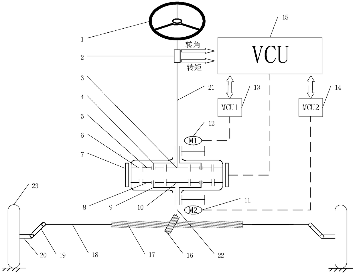
[0039] The multi-mode steering-by-wire device of the present invention includes a steering wheel unit 1, a steering wheel sensor 2 connected to the steering wheel unit 1 through an output shaft 22, a first planetary gear train, a second planetary gear train, and a pinion. 16. The pinion 16 is connected with the rack 17, and the steering tie rod 18, the trapezoidal arm 19, and the steering knuckle 20 are arranged symmetrically in sequence on both sides of the rack 17; the left and right wheels 23 are connected by the steering knuckle 20 on both sides.

[0040] The first planetary gear train...


PUM


Abstract

The invention discloses a multi-mode steer-by-wire device and belongs to the technical field of automobile steer-by-wire. According to the multi-mode steer-by-wire device, a second planet gear train and a first planet gear train are arranged on an output shaft of an automobile in sequence; the first planet gear train and the second planet gear train are correspondingly controlled by a motor; and amotor controller and a vehicle controller are arranged to control working modes of the first planet gear train and the second planet gear train. The invention further discloses a control method for the multi-mode steer-by-wire device; by correspondingly controlling the motor and an inner gear ring electromagnetic clutch, four different working modes of a pure mechanical steering mode, an electricpower steering mode, a steer-by-wire mode and an automatic driving mode are switched to; under other three modes except for the pure mechanical steering mode, a main shaft can be locked under the action of an electromagnetic brake when one motor is invalid; and meanwhile, another motor is started to be used as a power source; when the two motors are simultaneously invalid, the multi-mode steer-by-wire device automatically enters the pure mechanical steering mode without being additionally controlled; and therefore, the steering reliability is furthest guaranteed.

Description

technical field [0001] The invention belongs to the active steering of automobiles, and in particular relates to the technical field of steering-by-wire steering of automobiles, in particular to a multi-mode steering-by-wire device and a control method thereof. Background technique [0002] The intelligentization of automobiles is developing rapidly. Steering by wire is a key link in the development of intelligent automobiles, especially one of the necessary technologies for unmanned driving. The steer-by-wire technology has gradually matured and has been applied to a small number of models. The steer-by-wire system requires redundancy and fault-tolerant functions. Not only does it need to implement diagnostic and fault-tolerant control algorithms on the software, but it also requires redundant design of the hardware, which leads to complex hardware layout, high cost, and low hardware utilization of the steer-by-wire system. [0003] At present, there have been many researc...

Claims


Application Information

Patent Timeline
Patent Type & Authority Applications(China)
IPC IPC(8): B62D5/04B62D3/02B62D3/12B62D6/00B62D137/00
CPCB62D3/02B62D3/12B62D5/04B62D6/00
Inventor 金智林梁为何李静轩赵万忠陈国钰严正华
Owner NANJING UNIV OF AERONAUTICS & ASTRONAUTICS
Why Eureka
Try Eureka