Supercharge Your Innovation With Domain-Expert AI Agents!

Filling material feeding device and system

A technology of feeding device and filling material, applied in the direction of filling material, safety device, packaging, etc., can solve the problems of low measurement accuracy, poor feeding, sound wave interference, etc., and achieve the effect of high measurement accuracy and smooth feeding

Pending Publication Date: 2018-11-06
CHINA MINMETALS CHANGSHA MINING RES INST
View PDF7 Cites 0 Cited by
  • Summary
  • Abstract
  • Description
  • Claims
  • Application Information

AI Technical Summary

Problems solved by technology

There are some disadvantages in this cement feeding system: First, the ultrasonic material level gauge cannot accurately measure the material level height in the cement silo (or cement powder silo), because the ultra-deep wave is reflected by emitting sound waves, and the signal is transmitted Back to calculate the height of the material level, but due to the large dust in the bin during the feeding process or the actual unloading process of the filling material, the sound wave interference is large, so the height cannot be accurately measured
Secondly, the vibrating motor used in the cone of the cement silo (or cement powder silo) for vibrating blanking is not effective, and the arching inside the silo is serious, which will cause unsmooth blanking
Then, the screw feeder and screw electronic scale are used to implement the order of feeding first and then measuring. The measurement accuracy is not high, mainly because the electronic scale is arranged at the lower end of the feeder, and the weighing accuracy will be affected by the feeding frequency of the feeder and the lower end. Influenced by the material situation, in addition, the length of the electronic scale is relatively long, which will also affect the accuracy

Method used


Image

  • Filling material feeding device and system
  • Filling material feeding device and system
  • Filling material feeding device and system

Examples


no. 1 example

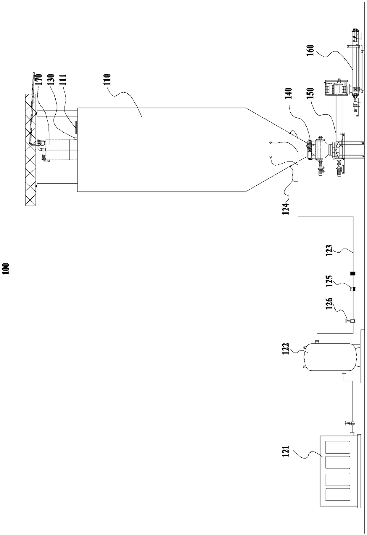
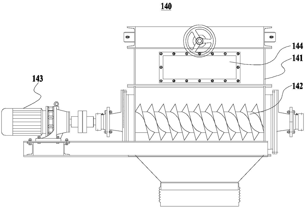
[0032] Please refer to figure 1 As shown, the present embodiment provides a filler feeding device 100, which includes a silo 110, and an arch breaking device for breaking the arch inside the silo 110. A radar level gauge 130 is installed on the top of the silo 110. The outlet of the bin 110 is equipped with a flow stabilization device 140, the outlet of the flow stabilization device 140 is connected with a micropowder scale 150, and a screw feeder 160 is arranged below the outlet of the micropowder scale 150. When cement is used as filling material, what is stacked in the silo 110 is cement, and the silo 110 at this time is the cement silo; Storehouse 110 is exactly glue solid powder storehouse. Usually, the main body of the silo 110 (cement silo or cement powder silo) is cylindrical, and the bottom is a cone, which is in an inverted cone shape; the feed port of the silo 110 is located at the top, and the discharge port is located at the end of the cone. cutting edge.

[00...

no. 2 example

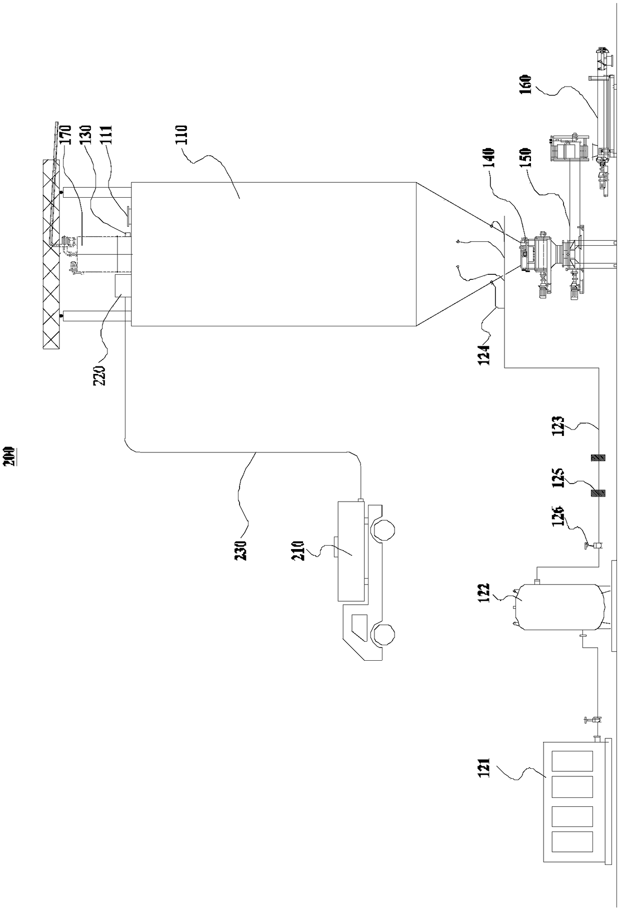
[0044] Please refer to image 3 As shown, the present embodiment provides a filling material feeding system 200, which includes a cement tank 210, a filter box 220 and the filling material feeding device 100 of the first embodiment, and the cement tank 210 is generally transported by a cement tank 210 truck to On site, the cement tank 210 communicates with the feed port of the filter box 220 through the soot blowing pipe 230 , and the discharge port of the filter box 220 communicates with the feed port of the silo 110 . The cement tank 210 is used to replenish the filling material to the silo 110, and then realize high-precision uniform feeding through the filling material feeding device 100. The filling material in the cement tank 210 first enters the filter box 220 for filtering treatment, and then enters the feed bin 110 from the filter box 220, which can ensure that the bulk materials or impurities in the filling material cannot enter the feed bin 110 (cement bin or glue s...


PUM


Abstract

The invention discloses a filling material feeding device and system, and relates to the technical field of filling in mining industry. The filling material feeding device comprises a material bin andan arch breaking device for conducting arch breaking on the interior of the material bin. A radar level gauge is mounted at the top of the material bin. A flow stabilizing device is mounted at a discharging outlet of the material bin. An outlet of the flow stabilizing device is connected with a micro-powder scale. A screw feeder is arranged below an outlet of the micro-powder scale. According tothe filling material feeding device, smooth feeding is ensured, and metering precision is high. The filling material feeding system comprises a cement tank, a filter box and the filling material feeding device. The cement tank communicates with a feeding inlet of the filter box. A discharging outlet of the filter box communicates with a feeding inlet of the material bin. The filling material feeding system is smooth in feeding and high in metering precision.

Description

technical field [0001] The invention relates to the technical field of mining filling, in particular to a filling material feeding device and system. Background technique [0002] The filling mining method refers to the mining method of filling the goaf with filling materials while carrying out ore dropping, transportation and other operations. The purpose of filling is to support the two sides of rocks in the goaf, and to create a foothold for the continuation of the layered mining above. It is suitable for deposits where the ore and surrounding rock are not stable and large exposure is not allowed; deposits whose surface needs to be protected; rare precious metals or high-grade deposits; spontaneous combustion sulfide deposits; deposits with complex occurrence conditions, etc. In the technical field of filling technology in the mining industry, cement or cement powder is often used as filling material. [0003] The structure of most of the cement feeding systems currentl...

Claims


Application Information

Patent Timeline
IPC IPC(8): E21F15/06B65G65/46B65D88/70B65D90/48
CPCE21F15/06B65D88/70B65D90/48B65G65/46B65G2201/045
Inventor 彭亮康瑞海王旭仵锋锋江科李鑫
Owner CHINA MINMETALS CHANGSHA MINING RES INST
Features
  • R&D
  • Intellectual Property
  • Life Sciences
  • Materials
  • Tech Scout
  • Unparalleled Data Quality
  • Higher Quality Content
  • 60% Fewer Hallucinations
Learn More