Rear-end-ignition pulse detonation combustion engine

A technology of pulse detonation and engine system, applied in the direction of machine/engine, gas turbine device, mechanical equipment, etc., can solve the problems of low ignition energy, long DDT pipe section, system complexity, etc., to reduce fluctuation and improve stability. Effect

Inactive Publication Date: 2018-11-06
NORTHWESTERN POLYTECHNICAL UNIV
View PDF0 Cites 6 Cited by
  • Summary
  • Abstract
  • Description
  • Claims
  • Application Information

AI Technical Summary

Problems solved by technology

[0003] Since the generation of detonation waves is intermittent and periodic, each detonation combustion chamber usually requires a periodic ignition source. Currently, the main ignition sources used include spark ignition, plasma ignition, pre-detonation tube ignition, etc. , each detonation chamber requires an independent ignition system and corresponding control system, which brings complexity to the system; at the same time, these ignition methods have low ignition energy and require a long DDT pipe section; for some commonly used The explosive mixture, the way of ignition with small energy can not detonate well
[0004] During the filling process of the explosive mixture after detonation combustion, affected by the ignition frequency, some explosive mixtures will not participate in the combustion and heat release, but will be directly discharged into the atmosphere, which will cause certain waste and environmental pollution

Method used


Image

  • Rear-end-ignition pulse detonation combustion engine
  • Rear-end-ignition pulse detonation combustion engine
  • Rear-end-ignition pulse detonation combustion engine

Examples


Embodiment Construction

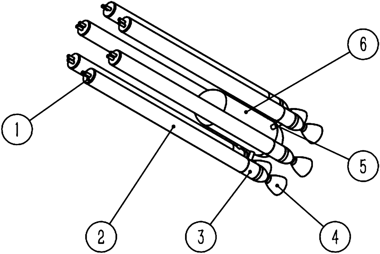
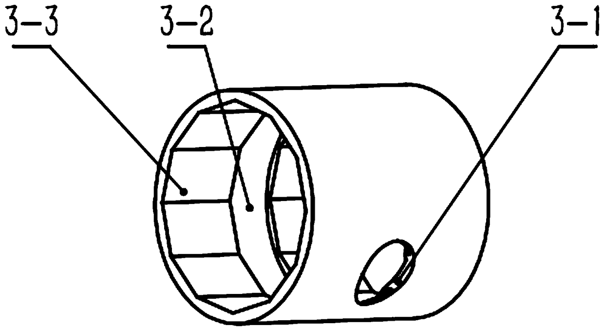
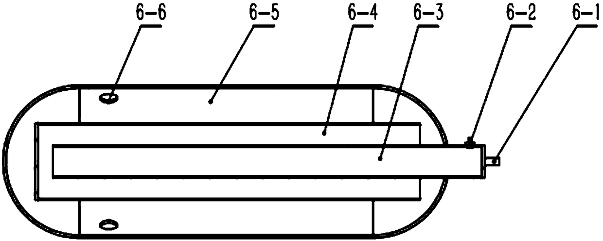
[0019] see Figure 1-Figure 5 , a multi-tube parallel pulse detonation engine system with large heat flow ignition at the rear end, each component is in accordance with figure 1 with Figure 4 Assembled as shown, the whole system includes explosive gas mixture and isolation gas supply device, ignition and detonation device, and multiple parallel detonation chamber systems. The fuel supply system is composed of oxidant storage tank, isolation gas storage tank, fuel storage tank, explosive mixture splitter, isolation gas splitter, high-frequency solenoid valve at the entrance of detonation chamber, and the connecting pipelines and valve systems of these components. In addition, it also includes a corresponding valve switch phase control system. Each detonation chamber system includes a detonation chamber inlet 1, a detonation chamber 2, an igniter 3, a nozzle 4 and a jet propagation pipe 5; The most downstream of the airflow of the shock chamber 2; the igniter 3 is located be...


PUM


Abstract

The invention discloses a rear-end large heat flow ignition pulse detonation engine system comprising an explosive mixed gas and isolation gas supply system, an ignition initiation system and detonation chamber systems. Each detonation chamber system comprises a detonation chamber inlet 1, a detonation chamber 2, an igniter 3, a spray pipe 4 and a jet spread pipe 5. Each igniter 3 is connected with a high pressure generator 6. The multiple detonation combustion chamber systems are distributed around the high pressure generator 6 circumferentially. The detonation chambers 2 work basically independently and do not disturb one another. The high pressure generator 6 comprises a high pressure generator inlet 6-1, a sparking plug 6-2, a detonator 6-3, a two-level detonation pipe 6-4, a high pressure generator shell 6-5 and a high pressure generator outlet 6-6. During work, high-temperature high-pressure gas generated by the high pressure generator 6 enters the igniters 3 through the jet spread pipes 5, and an explosive mixture is ignited.

Description

technical field [0001] The invention relates to the technical field of engines, in particular to a pulse detonation engine system. Background technique [0002] Detonation engine technology is a future engine technology with great development potential. Compared to other forms of combustion, detonation waves travel very quickly and can generate extremely high pressures and temperatures. The propulsion system based on detonation combustion has a high advantage in thermal cycle efficiency and can be widely used in aerospace vehicles, especially supersonic vehicles. [0003] Since the generation of detonation waves is intermittent and periodic, each detonation combustion chamber usually requires a periodic ignition source. Currently, the main ignition sources used include spark ignition, plasma ignition, pre-detonation tube ignition, etc. , each detonation chamber requires an independent ignition system and corresponding control system, which brings complexity to the system; ...

Claims


Application Information

Patent Timeline
Patent Type & Authority Applications(China)
IPC IPC(8): F02K7/02F02K7/06F02C7/266
CPCF02K7/02F02C7/266F02K7/06
Inventor 范玮谭风光张启斌
Owner NORTHWESTERN POLYTECHNICAL UNIV
Why Eureka
Try Eureka