
Container packaging type mechanical seal for corrosion-resistant alkali pump

A mechanical seal and cartridge technology, applied to mechanical equipment, components of pumping devices for elastic fluids, pumps, etc., can solve problems such as uneven force, easy to wear, and reduced solid content, and achieve Easy to install and replace, safe and environmentally friendly to use, evenly dispersed and stable

Inactive Publication Date: 2018-11-06
ANHUI LUYUAN PUMP&VALVE CO LTD
View PDF1 Cites 3 Cited by
  • Summary
  • Abstract
  • Description
  • Claims
  • Application Information

AI Technical Summary

Problems solved by technology

[0002] The alkali pump is located at the bottom of the alkali washing tower during use, and the corrosion of pipes and equipment, as well as impurities and heavy component polymers in the pyrolysis gas are deposited at the bottom of the tower, while NaOH and H in the tower 2 S and CO 2 The components react to form Na 2 S, Na 2 CO 3 Crystals are produced, and the filter screen at the pump inlet is usually 40 mesh, which is often blocked in the actual production process. Evacuating the pump and reducing the filter screen can solve the problem of inlet blockage, but it also causes the lye entering the pump body to contain a large amount of impurities and Crystals, due to the self-flushing method, these impurities and crystals are deposited in the sealing cavity, blocking the gap between the moving ring, the moving ring seat, and the shaft sleeve, causing the axial movement of the moving ring to be inflexible or even stuck, and the spring due to Corroded and stuck, insufficient elasticity, can not provide the original design of the end face specific pressure, resulting in the sealing surface can not fit well, the balance of the liquid film is destroyed, so that the seal has micro leakage, as crystals and impurities enter the end face of the friction pair, the seal The surface is gradually worn, and the axial compensation of the moving ring is not effective, resulting in an increase in the leakage of the seal, which eventually leads to the complete failure of the seal;
[0003] In the technical data provided in the article "Failure Analysis and Improvement of Concentrated Alkali Pump Mechanical Seal" (Zhuang Yongfu), the reasons for the failure of the mechanical seal of the pump are analyzed, and corresponding improvement measures are given, including: (1) Machine modification The sealing mechanism adopts static ring compensation, selects Egger 3055 card-type single-end mechanical seal (cartridge type), and realizes precise centering through the automatic locking ring. The adjustable gland is directly used with common bolts, and the cartridge structure is installed Convenient, there is no medium side in the gap between the static ring and the bushing, ensuring the flexibility of the axial compensation of the static ring, the spring is located outside the auxiliary sealing ring, completely separated from the medium, and avoids corrosion and jamming of the spring; (2) Change the friction Secondary material, remove seal flushing and back cooling, cassette seal dynamic ring and static ring materials are made of tungsten carbide, which has extremely high strength and hardness, good wear resistance and corrosion resistance, so impurities and crystals are difficult to clean At the same time, the tungsten carbide friction pair has excellent thermal conductivity, a small linear expansion coefficient, and can maintain good sealing performance at higher temperatures. The auxiliary sealing ring is made of fluororubber FPM2461, which is corrosion-resistant and elastic. The temperature is 250°C; the service life is more than two years, but when in use, the solid content of the transportable medium is reduced, which cannot meet the transportation needs of high solid content media, and it is inevitable that the corrosive, toxic and harmful media will seep Leak into the atmosphere, with the continuous improvement of industrial production requirements for environmental protection, this technology can no longer meet the corresponding needs
[0004] The application number is 201310530974.6, which discloses a plastic pump built-in double-end mechanical seal structure, in which the first moving ring is installed on the back of the impeller, and the first static ring matching the first moving ring is set in the pump cover. Connect the static ring gland through the first spring, the first spring is stationary and not in contact with the medium, the pump cover is connected to the static ring gland, the impeller is fixed with a spring seat on the shaft on the impeller side of the principle of the static ring gland, and the spring The seat is provided with a second moving ring, and the contact surface of the second moving ring of the spring seat and the static ring gland is provided with a matching second static ring, and the second static ring and the second moving ring pass through the first ring on the spring seat. The second spring is pressed, and the double-end mechanical seal structure is adopted, which can increase the pressure of the coolant on the atmospheric side of the mechanical seal, which is greater than the pressure of the mechanical chamber, so as to ensure that the toxic, flammable and explosive medium does not leak out; but the seal is a split mechanical seal. The operation of assembly and replacement is relatively cumbersome; in the assembly process, due to the structural limitations of the shaft sleeve, it is easy to appear uneven force in the circumferential direction of the static ring when it is installed, and assembly errors are prone to occur when the impeller, shell, and bracket are installed, and the spring The amount of compression is easily affected, resulting in the situation that the specific pressure of the end face fluctuates during use. When the specific pressure of the end face is too large, it is easy to wear and affect the service life. If the specific pressure of the end face is too small, leakage may occur and the seal cannot be satisfied. Requirements, therefore, need to further improve on this basis

Method used


Image

  • Container packaging type mechanical seal for corrosion-resistant alkali pump
  • Container packaging type mechanical seal for corrosion-resistant alkali pump
  • Container packaging type mechanical seal for corrosion-resistant alkali pump

Examples


Embodiment Construction

[0022] The present invention will be further described below in conjunction with the accompanying drawings.

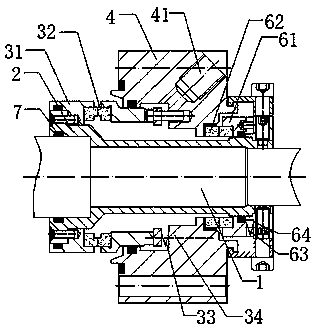
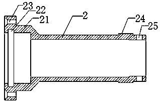
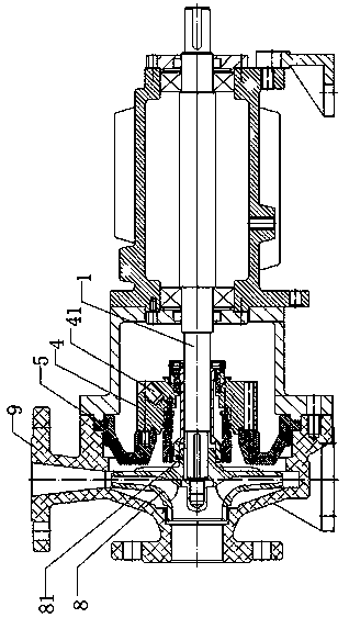
[0023] Such as Figure 1-3 As shown in , a cartridge mechanical seal for corrosion-resistant alkali pumps includes a shaft sleeve 2, a gland 4, a medium end seal located inside the gland 4, and an atmospheric end water seal located outside the gland 4. The gland 4 There is a cooling water port 41 on the top, the bushing 2 is set outside the pump shaft 1, the impeller 8 is set on the end of the pump shaft 1 through the impeller hub 81, and the side of the bushing 2 close to the impeller 8 is provided with an inclined surface A connected stepped structure 21, the side of the stepped structure 21 close to the impeller 8 is provided with an annular groove 22 opening towards the pump shaft 1, the stepped structure 21 is provided with an axial positioning hole 23, and the shaft sleeve 2 The side away from the impeller 8 is provided with a convex structure 24 and a radial po...


PUM


Abstract

The invention relates to a container packaging type mechanical seal for an alkali pump, in particular to the container packaging type mechanical seal for the corrosion-resistant alkali pump. The container packaging type mechanical seal for the corrosion-resistant alkali pump comprises a shaft sleeve, a gland, a medium end seal and an atmosphere end water seal, wherein the medium end seal is located on the inner side of the gland, and the atmosphere end water seal is located on the outer side of the gland. An impeller is arranged at the end of a pump shaft through an impeller hub, the side, close to the impeller, of the shaft sleeve is provided with a step type structure connected with the shaft sleeve through an inclined face, the side, close to the impeller, of the step type structure isprovided with an annular groove with the opening facing the pump shaft, the step type structure is provided with an axial positioning hole, and the side, away from the impeller, of the shaft sleeve isprovided with a convex structure and a radial positioning hole. Compared with the prior art, the container packaging type mechanical seal for the corrosion-resistant alkali pump has the following advantages that the container packaging type mechanical seal can be used for conveying a medium with the medium solid content being 40% after being installed in the alkali pump, the shaft sleeve structure is reasonably designed, the container packaging type mechanical seal is used for conveying the concentrated alkali medium, the sealing effect is goof, use is safe and environmentally friendly, the environmental protection requirements of industrial production are met, the service life is long, the treatment cost of harmful gas is saved, and economic benefits are remarkable.

Description

technical field [0001] The invention relates to a cartridge-type mechanical seal for an alkali pump, in particular to a cartridge-type mechanical seal for a corrosion-resistant alkali pump. Background technique [0002] The alkali pump is located at the bottom of the alkali washing tower during use, and the corrosion of pipes and equipment, as well as impurities and heavy component polymers in the pyrolysis gas are deposited at the bottom of the tower, while NaOH and H in the tower 2 S and CO 2 The components react to form Na 2 S, Na 2 CO 3 Crystals are produced, and the filter screen at the pump inlet is usually 40 mesh, which is often blocked in the actual production process. Evacuating the pump and reducing the filter screen can solve the problem of inlet blockage, but it also causes the lye entering the pump body to contain a large amount of impurities and Crystals, due to the self-flushing method, these impurities and crystals are deposited in the sealing cavity, bl...

Claims


Application Information

Patent Timeline
Patent Type & Authority Applications(China)
IPC IPC(8): F04D29/12F04D29/02F04D29/06F04D29/58C10M173/00C10N30/06
CPCC10M173/00C10M2207/126C10M2207/289C10M2207/32C10M2215/06C10M2215/221C10M2219/044C10N2030/06C10N2030/36F04D29/026F04D29/061F04D29/126F04D29/586
Inventor 凤元军
Owner ANHUI LUYUAN PUMP&VALVE CO LTD
Learn More