Supercharge Your Innovation With Domain-Expert AI Agents!

Ceramic antenna manufacturing method, ceramic antenna and ceramic back cover

A technology of ceramic antenna and manufacturing method, which is applied in the direction of antenna support/installation device, antenna grounding switch structure connection, radiation element structure form, etc., can solve the problem of insufficient antenna radiation clearance space, etc., to improve antenna performance and improve wireless experience effect, guaranteed headroom and height effect

Inactive Publication Date: 2018-11-06
SHENZHEN TRUSTED HUACHENG COMM TECH CO LTD
View PDF8 Cites 1 Cited by
  • Summary
  • Abstract
  • Description
  • Claims
  • Application Information

AI Technical Summary

Problems solved by technology

[0003] The technical problem to be solved by the present invention is to provide a method for manufacturing a ceramic antenna, a ceramic antenna and a ceramic back cover in view of the defect that the above-mentioned antenna space is compressed in the prior art and the antenna radiation clearance space is not enough

Method used


Image

  • Ceramic antenna manufacturing method, ceramic antenna and ceramic back cover
  • Ceramic antenna manufacturing method, ceramic antenna and ceramic back cover
  • Ceramic antenna manufacturing method, ceramic antenna and ceramic back cover

Examples


Embodiment Construction

[0024] In order to have a clearer understanding of the technical features, purposes and effects of the present invention, the specific implementation manners of the present invention will now be described in detail with reference to the accompanying drawings.

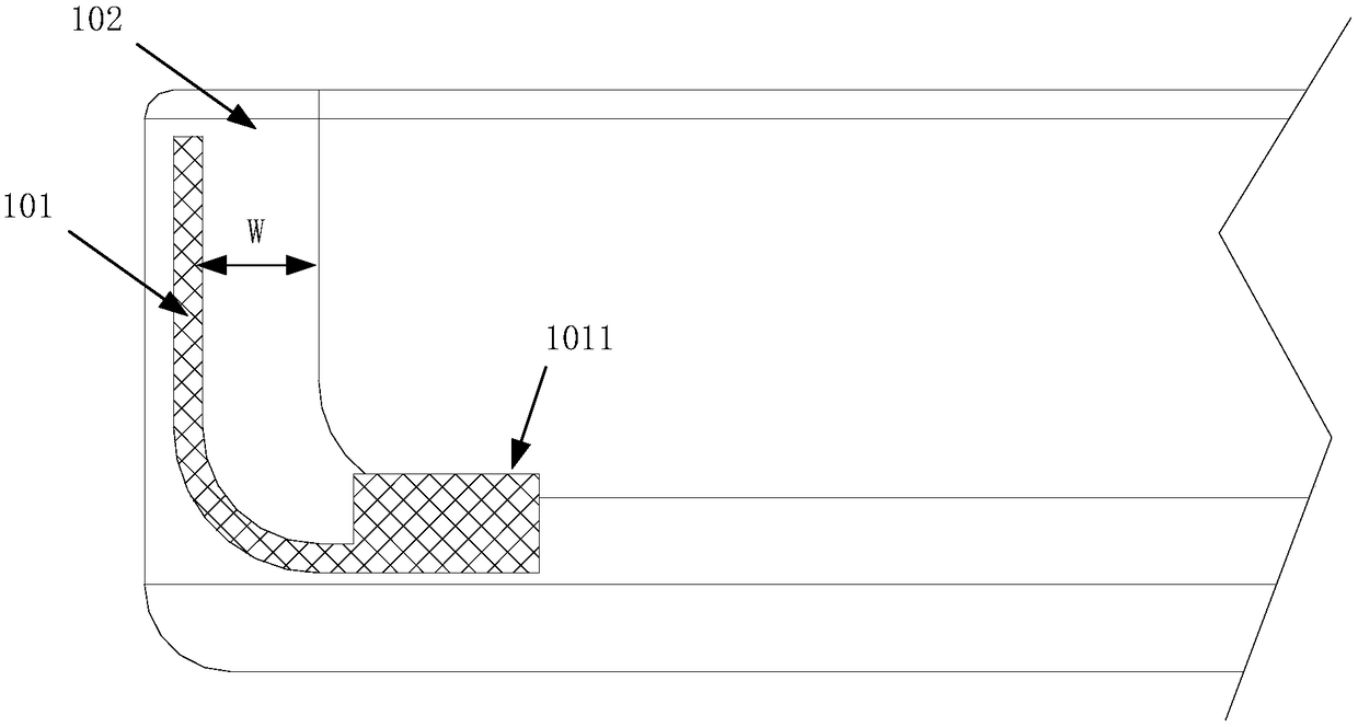
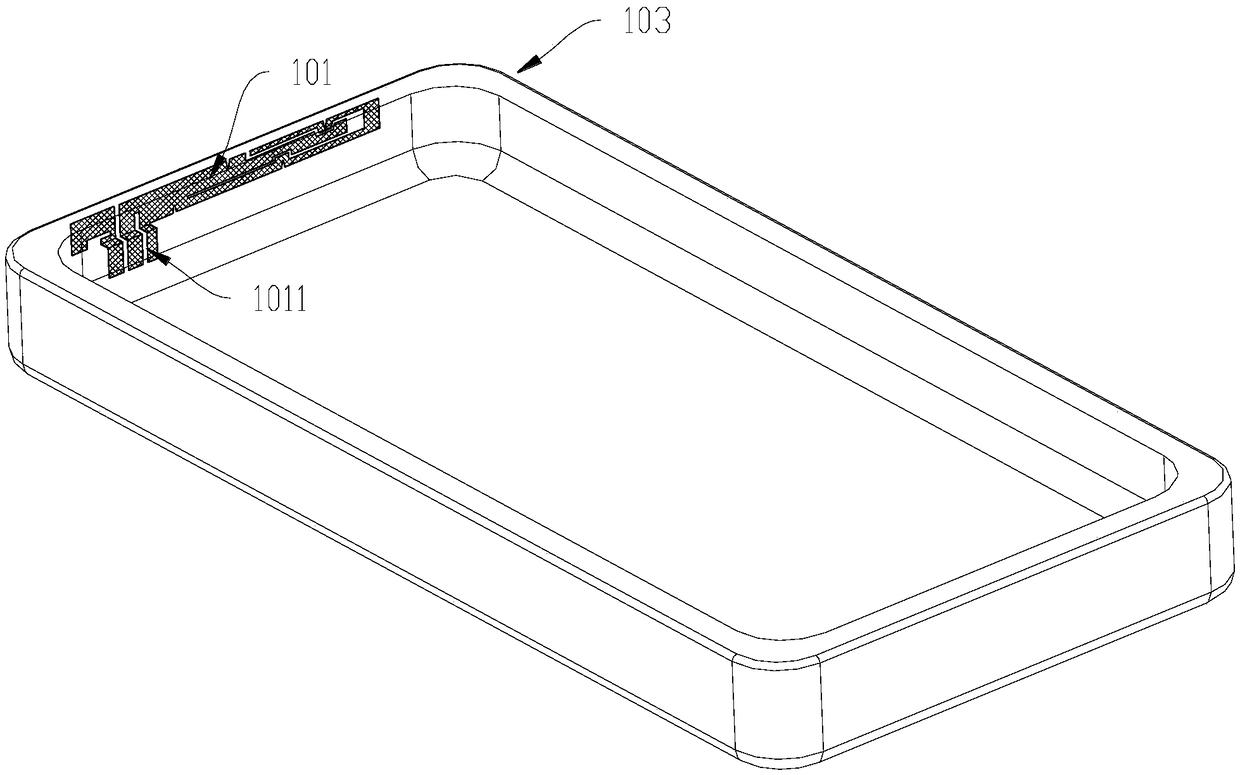
[0025] Such as figure 1 As shown, in an embodiment of a ceramic antenna manufacturing method of the present invention, the following steps are included:

[0026] S1. Mix the ceramic powder and the polymer adhesive to form a slurry; specifically, mix the ceramic powder and the polymer adhesive in proportion to form a fluid mixed slurry. The ceramics here include ceramic materials such as zirconia, and ceramic powders generally use ceramic materials with low dielectric constants. This has minimal impact on the antenna. For example, CaMgSi2O6 ceramics are selected, which is a low dielectric constant ceramic material with excellent performance, which is convenient for antenna radiation.

[0027] S2. The slurry is injecte...


PUM

PropertyMeasurementUnit
melting pointaaaaaaaaaa

Abstract

The invention relates to a ceramic antenna manufacturing method, a ceramic antenna and a ceramic back cover. The ceramic antenna manufacturing method of the invention includes the following steps that: S1, ceramic powder and a polymer adhesive are mixed to form a slurry; S2, an injection device is adopted to inject the slurry into an injection mold provided with an antenna body, so that a slurry mixture can be formed, a signal overflow point of the antenna body, which is used for externally connecting a circuit or ground, protrudes out from the surface of the slurry mixture; S3, the polymer adhesive is removed from the slurry mixture through a catalyst, and high temperature sintering is performed on the slurry mixture; and S4, conductive treatment is performed on the signal overflow point.With the method provided by the embodiments of the invention adopted, the clearance space and height of the antenna can be ensured to the greatest extent when the space of a whole unit is limited.

Description

technical field [0001] The invention relates to the field of antennas, and more specifically, to a method for manufacturing a ceramic antenna, a ceramic antenna and a ceramic back cover. Background technique [0002] With the development of communication technology, 5G communication will be initially commercialized. The salient features of 5G signals are faster signal transmission speed, a large number of antennas, the wavelength of millimeter waves is very short, and the interference from metals is more serious. Ceramics have "innate Advantage". With the gradual popularization of ceramics in the field of mobile phone functions such as fingerprint identification and wireless charging, ceramic materials have the characteristics of no signal shielding, high hardness, strong appearance, mechanical properties close to metal materials, and excellent heat dissipation, which will become the mobile phone companies entering the 5G era. key choice. At the same time, the antenna desi...

Claims


Application Information

Patent Timeline
Patent Type & Authority Applications(China)
IPC IPC(8): H01Q1/12H01Q1/22H01Q1/36H01Q1/50
CPCH01Q1/12H01Q1/22H01Q1/36H01Q1/50
Inventor 刘峻
Owner SHENZHEN TRUSTED HUACHENG COMM TECH CO LTD
Features
  • R&D
  • Intellectual Property
  • Life Sciences
  • Materials
  • Tech Scout
  • Unparalleled Data Quality
  • Higher Quality Content
  • 60% Fewer Hallucinations
Learn More