Efficient revolving furnace gas rotational flow dewatering device and dewatering method thereof

A technology of dehydration device and coal cyclone, which is applied in the direction of swirl device and the device whose axial direction of swirl can be reversed, etc., can solve the problem of outer cylinder being corroded, shorten the separation time of gas and water, and evenly distribute the flow field , The effect of improving the dehydration efficiency

Pending Publication Date: 2018-11-09
ANHUI UNIVERSITY OF TECHNOLOGY
View PDF9 Cites 4 Cited by
  • Summary
  • Abstract
  • Description
  • Claims
  • Application Information

AI Technical Summary

Problems solved by technology

[0007] Aiming at the problems of uneven air distribution, secondary entrainment of flue gas and slow gas-water separation in the existing cyclone dust collector, the dehydration efficiency is not particularly high, the present invention provides a high-efficiency converter gas cyclone dehydration device and its dehydration method, the present invention optimizes the structure of the cyclone dehydrator without changing the structure of the outer cylinder and without significantly increasing the resistance, which not only improves the dehydration efficiency, but also improves the recovery quality and recovery rate of gas, and improves the efficiency of the fan. Use effect, prolong the cleaning cycle of the fan, and also improve the problem of erosion on the inner side of the outer cylinder

Method used


Image

  • Efficient revolving furnace gas rotational flow dewatering device and dewatering method thereof
  • Efficient revolving furnace gas rotational flow dewatering device and dewatering method thereof
  • Efficient revolving furnace gas rotational flow dewatering device and dewatering method thereof

Examples


Embodiment 1

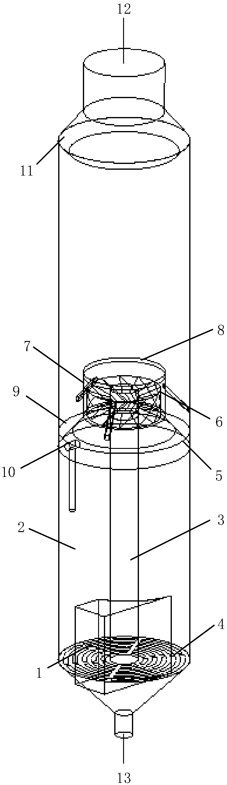
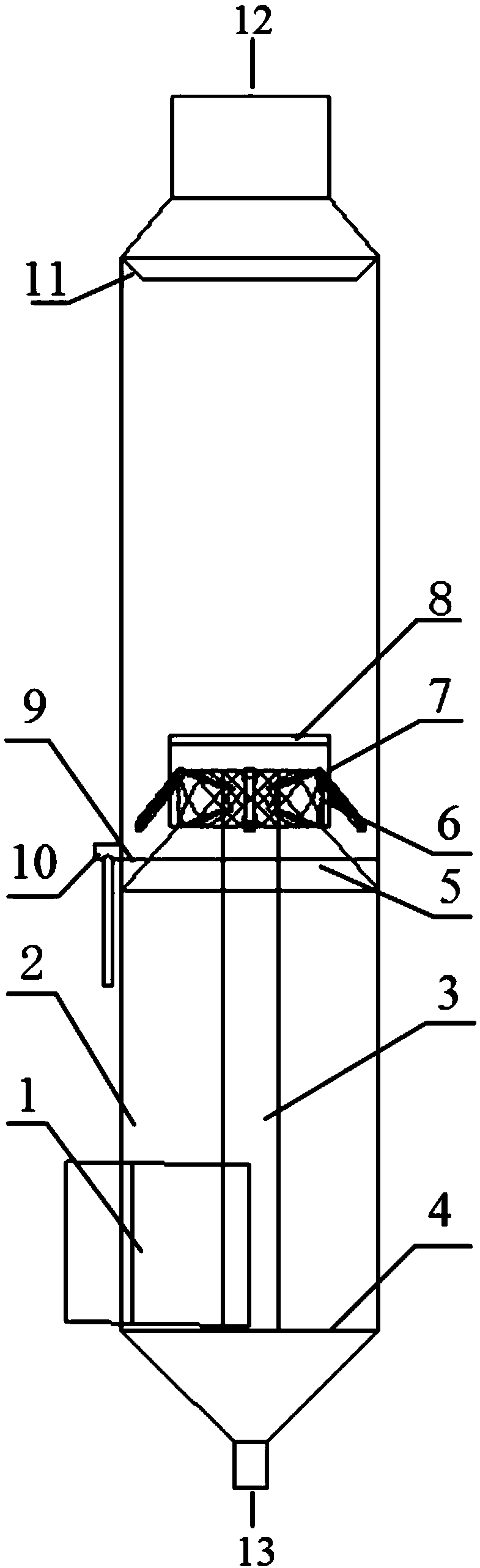
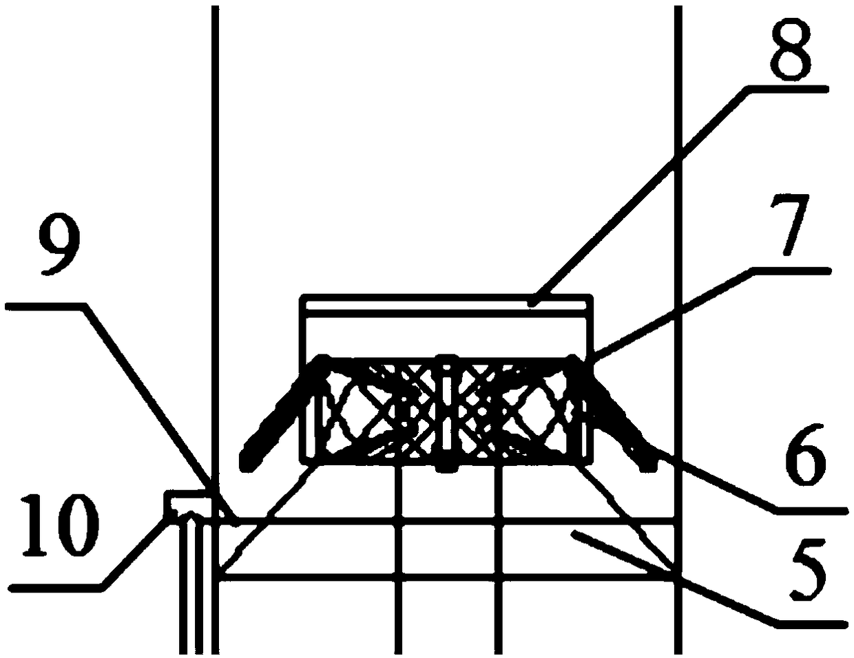
[0036] In conjunction with the accompanying drawings, this embodiment is suitable for a high-efficiency converter gas cyclone dehydration device for converter gas purification and recovery, including a flue gas inlet section 1, an outer cylinder wall 2, a gas guide column 3, an overflow plate 4, and a shrink tube 5. Cyclone 6, inner cylinder wall 7, water retaining ring 8, liquid sump 9, drain pipe 10 and water retaining ring 11. The flue gas inlet section 1 is arranged at the lower part of the outer cylinder wall 2, and the flue gas enters the dehydrator tangentially so as to generate swirl gas. see figure 2 , The flue gas inlet section 1 has a slightly inclined downward angle, so as to facilitate the separated water droplets before entering the dehydrator to flow into the drain bucket at the bottom of the dehydrator.

[0037] see figure 1 , The bottom of the outer cylinder wall 2 is provided with an overflow plate 4, and an annular overflow gap is opened on the overflow p...


PUM


Abstract

The invention discloses an efficient revolving furnace gas rotational flow dewatering device and a dewatering method thereof and belongs to the technical field of steel dust removal. The efficient revolving furnace gas rotational flow dewatering device comprises an outer barrel wall, a gas guiding pillar, an overflow plate, a contracting pipe and a cyclone. The overflow plate is arranged at the bottom of the outer barrel wall. The gas guiding pillar is arranged on the upper portion of the overflow plate and located at the central axis of the outer barrel wall. The gas guiding pillar extends toan inlet of the cyclone in the height direction. The bottom end of the cyclone is connected with the contracting pipe. An inner barrel wall is arranged outside the cyclone in a sleeving manner and fixed to the outer barrel wall. The overflow plate is provided with an annular overflow gap. By means of the efficient revolving furnace gas rotational flow dewatering device and the dewatering method thereof, under the conditions that the structure of an outer barrel body is not changed and the resistance is not increased obviously, structural optimization is conducted on a rotational flow dewaterer; dewatering efficiency can be improved, thus, the gas recycling quality is improved, and the gas recycling rate is increased; the application effect of a fan is improved, and the cleaning cycle of the fan is prolonged; and the problem that the inner side of the outer barrel body is corroded can be solved.

Description

technical field [0001] The invention relates to the technical field of iron and steel dedusting, and more specifically relates to a high-efficiency converter gas cyclone dehydration device and a dehydration method thereof, which is suitable for converter gas purification and recovery. Background technique [0002] During converter smelting, a large amount of high-temperature flue gas containing CO will be produced. Because of its large dust content, it must be purified to obtain effective resource recovery and utilization. However, the purified gas has a large water content, and dust is still wrapped in the water. If the dehydration effect is not good, it will not only affect the gas recovery quality and recovery rate, but also cause the fan to stick to dust if the moisture is brought into the fan, which will affect the use effect of the fan and shorten the cleaning cycle of the fan. [0003] Dehydrators commonly used in converter gas purification and recovery systems includ...

Claims


Application Information

Patent Timeline
Patent Type & Authority Applications(China)
IPC IPC(8): B04C5/181B04C5/103
CPCB04C5/103B04C5/181
Inventor 钱付平梁梅朱景晶张天
Owner ANHUI UNIVERSITY OF TECHNOLOGY
Why Eureka
Try Eureka