Improved hydrogen gas production reactor

A technology of a reaction kettle and a reaction kettle body, which is applied in the field of improved hydrogen production reaction kettles, can solve problems such as hydrogen leakage, pipeline blockage, and time-consuming repairs, and achieves a high rate of hydrogen collection, prevents hydrogen leakage, and prevents blockages. The effect of the pipeline

Inactive Publication Date: 2018-11-13
张新雨
View PDF6 Cites 11 Cited by
  • Summary
  • Abstract
  • Description
  • Claims
  • Application Information

AI Technical Summary

Problems solved by technology

[0003] The hydrogen production reaction kettle is a common reaction kettle. When preparing hydrogen, a specific catalyst is often used to speed up the reaction rate of hydrogen. Decomposition of other reagents, resulting in reduced activity of the catalyst, so the catalyst needs to be replaced frequently, and the catalyst is generally opened by manually opening the feed port of the reactor, and then the catalyst is put into the reactor, and when the reactor is in Opening the feed port during work will often cause a certain amount of hydrogen leakage, wasting hydrogen energy, and the hydrogen generated during hydrogen production often contains certain reactant impurities or product impurities. In the case of pipelines, after a long time, the inner surface of the pipeline will be fouled, which will affect the hydrogen collection efficiency, and even cause serious pipeline blockage, which is very time-consuming to repair
When the existing hydrogen production reactor is producing hydrogen, some air will often remain inside the reactor, and a certain amount of air will also remain inside the same pipeline and hydrogen collection device. Air and hydrogen are mixed during hydrogen production, making the collected production Hydrogen is not pure, so we propose an improved hydrogen production reactor

Method used


Image

  • Improved hydrogen gas production reactor
  • Improved hydrogen gas production reactor
  • Improved hydrogen gas production reactor

Examples


Embodiment Construction

[0018] The technical solutions in the embodiments of the present invention will be clearly and completely described below in conjunction with the accompanying drawings in the embodiments of the present invention. Obviously, the described embodiments are only a part of the embodiments of the present invention, rather than all the embodiments.

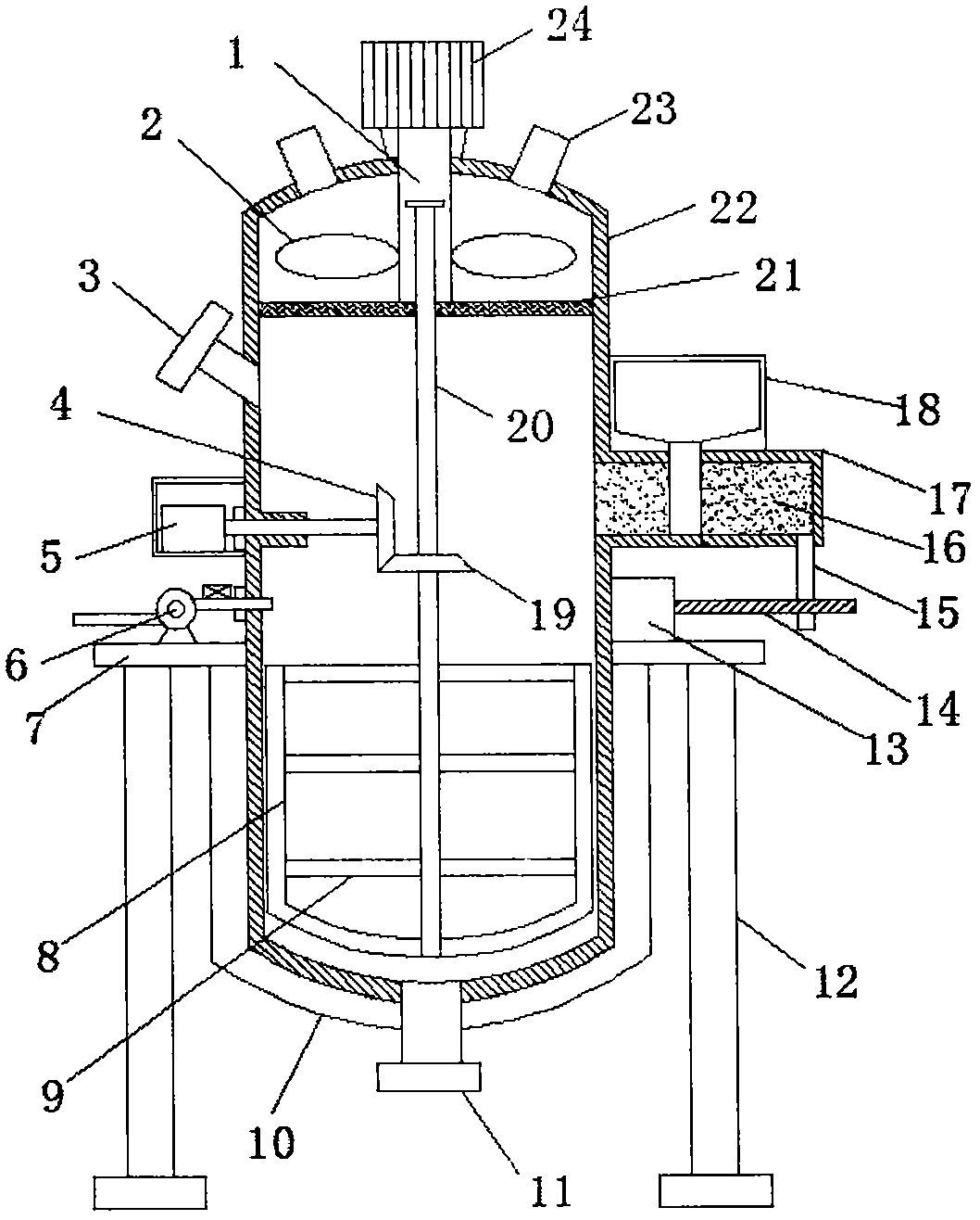
[0019] Reference Figure 1-4 , An improved hydrogen production reactor, comprising a reactor body 22, the top side wall of the reactor body 22 is provided with two symmetrically arranged air outlets 23, the bottom end of the reactor body 22 and the bottom end side wall are both provided There is a heating plate 10, the bottom center of the reactor body 22 is provided with a discharge port 11, and the discharge port 11 passes through the heating plate 10 to communicate with the inside of the reactor body 22, and the side wall of the reactor body 22 is welded There are four evenly distributed protruding plates 7, and the bottom ends of the pr...


PUM


Abstract

The invention discloses an improved hydrogen gas production reactor, comprising a reactor body, wherein two symmetrical air outlets are formed in the side wall at the top end of the reactor body, a heating plate is arranged on each of the bottom end and the side wall at the bottom end of the reactor body, a discharge opening is formed in the center of the bottom end of the reactor body, the discharge opening penetrates through the heating plate to be communicated with the inside of the reactor body, four uniformly distributed protruding plates are arranged on the side wall of the reactor bodyin a welding manner, vertically arranged supporting columns are arranged at the bottom ends of the protruding plates in the welding manner, an exhaust fan is fixedly arranged at the top end of one protruding plate by a bolt, the exhaust opening of the exhaust fan extends to the inside of the reactor body, and a second driving motor is fixedly arranged at the top end of the other protruding plate by a bolt. The reactor has the advantages of being simple in structure, reasonable in design, free of leakage of hydrogen gas during adding of a catalyst, and simultaneously is capable of preventing impurities in the hydrogen gas from blocking a pipeline and high in hydrogen gas collecting rate.

Description

Technical field [0001] The present invention relates to the technical field of reactors, in particular to an improved hydrogen production reactor. Background technique [0002] The broad understanding of the reactor is a container with physical or chemical reactions. Through the structural design and parameter configuration of the container, the heating, evaporation, cooling and low-speed mixing functions required by the process are realized. The reactor is widely used in petroleum, chemical, Rubber, pesticides, dyes, medicines, foods, pressure vessels used to complete vulcanization, nitrification, hydrogenation, alkylation, polymerization, condensation and other processes, such as reactors, reaction pots, decomposition pots, polymerization kettles, etc.; materials generally contain carbon Manganese steel, stainless steel, zirconium, nickel-based (Hastelloy, Monel, Inconel) alloys and other composite materials. [0003] Hydrogen production reactor is a common type of reactor. When...

Claims


Application Information

Patent Timeline
Patent Type & Authority Applications(China)
IPC IPC(8): B01J19/18B01J4/00C01B3/02
CPCB01J4/001B01J19/0013B01J19/0053B01J19/18B01J2204/005B01J2219/00135C01B3/02
Inventor 张新雨
Owner 张新雨
Why Eureka
Try Eureka