Preheating pyrolysis furnace

A technology of pyrolysis and furnace body, which is applied in the direction of pyrolysis treatment of sludge, coke oven, special form of dry distillation, etc. It can solve the problems of high heat transfer resistance of the upper layer material, short time of entering the furnace, uneven temperature of the reaction layer, etc., to achieve Accelerate the pyrolysis reaction rate, increase the output, and improve the effect of sludge treatment efficiency

Pending Publication Date: 2018-11-13
江苏俊镕环保设备有限公司
View PDF0 Cites 0 Cited by
  • Summary
  • Abstract
  • Description
  • Claims
  • Application Information

AI Technical Summary

Problems solved by technology

The time for the sludge on the upper part of the material layer to enter the furnace is short, the heating is insufficient, and the temperature cannot reach the minimum temperature required for the pyrolysis reaction, and its reaction rate is significantly lower than that of the lower part of the material layer.
Although the reaction rate of the lower layer is faster and the temperature is higher, the material in the fixed bed thermal cracking furnace is not in a fluidized state, the internal mixing effect of the reaction material layer is poor, and the heat transfer resistance of the material with high temperature in the lower layer to the upper layer is very large
The above reasons together lead to the slow heating of materials and uneven temperature of the reaction layer in the traditional fixed-bed thermal cracking furnace, which eventually lead to the low space utilization rate of the traditional thermal cracking furnace, low combustion efficiency, and the sludge treatment capacity is not up to expectations
[0006] Therefore, there is a lack of a thermal cracking furnace in the prior art, which can quickly heat the sludge into the furnace, so that the sludge can meet the temperature conditions of the cracking reaction and improve the sludge treatment efficiency.

Method used


Image

  • Preheating pyrolysis furnace
  • Preheating pyrolysis furnace
  • Preheating pyrolysis furnace

Examples


Embodiment Construction

[0032] In order to enable those skilled in the art to better understand the technical solutions of the present invention, the present invention will be further described in detail below in conjunction with specific embodiments.

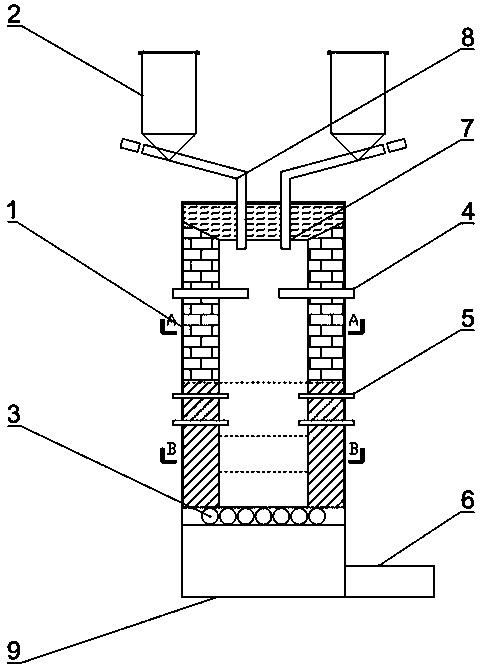
[0033] Embodiments of the present invention provide a preheating type pyrolysis furnace, such as figure 1 shown, including:

[0034] Furnace body 1, hopper 2, roller slag breaker 3, first nozzle 4, second nozzle 5, air induction pipe 6, feed inlet 7, feed pipe 8, slag discharge outlet 9.

[0035] A feed port 7 is arranged on the top of the furnace body 1, and the hopper 2 is connected to the feed port 7 through a feed pipe 8 and sealed.

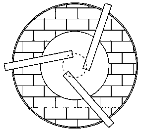
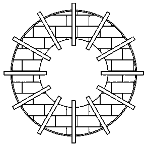
[0036] The furnace body 1 is a hollow cylinder with refractory bricks laid inside. A plurality of first nozzles 4 are arranged below the feed inlet 7, and the first nozzles 4 are arranged at an equal circumferential angle along the section direction of the furnace body 1, and one end of the first nozzles 4 extends ...


PUM


Abstract

The invention discloses a preheating pyrolysis furnace, and relates to the field of sludge treatment. The preheating pyrolysis furnace comprises a furnace body, a hopper, a double-roller slag crusher,a first spray nozzle, a second spray nozzle, a gas guide pipe, a feeding hole, a feeding pipe and a slag discharge hole, wherein the feeding hole is formed at the upper end of the furnace body and iscommunicated with the hopper; the slag discharge hole is formed in the bottom of the furnace body; the first spray nozzle is arranged near the feeding hole, and is used for spraying a high-temperature gas preheated material; a material preheating area is formed in the space at the upper part in the furnace body; the second spray nozzle is used for spraying water vapor and an oxidant, and is arranged at the lower part of the furnace body together with the gas guide pipe of synthesis gas; the double-roller slag crusher is arranged at the lower part of the furnace body and is used for supportinga sludge layer to form a pyrolysis reaction area, and is used for crushing the sludge residue left after the reaction. The preheating pyrolysis furnace provided by the invention fully utilizes the thermal energy of sludge, and generates high value-added combustible gas by means of thermal cracking; the pyrolysis furnace can be rapidly heated, so that the sludge in the furnace body rapidly reachesa cracking reaction temperature and fully reacts; therefore, the sludge treatment efficiency is improved.

Description

technical field [0001] The invention relates to the field of sludge treatment, in particular to a preheating type thermal cracking furnace. Background technique [0002] Sludge is produced during municipal sewage treatment. These sludges are complex in composition and contain heavy metal salts, bacteria and parasite eggs that are harmful to humans and the environment. With the increasing level of urbanization in our country, a large amount of sludge, a by-product of the city, needs to be treated urgently. [0003] At present, the mainstream sludge treatment methods at home and abroad are mainly incineration, pyrolysis and thermal cracking. Direct combustion of sludge can easily produce air pollutants such as dioxins, nitrogen oxides, and particulate matter. In contrast, through thermal cracking or pyrolysis treatment of sludge, combustible gas and tar can be obtained, and wastes such as heavy metal salts that are difficult to handle can be easily collected in the form of ...

Claims


Application Information

Patent Timeline
IPC IPC(8): C02F11/10C10B53/00
CPCC10B53/00C02F11/10
Inventor 许国忠葛琎许诺希陆敏葛俊旭
Owner 江苏俊镕环保设备有限公司
Why Eureka
Try Eureka