Precast plate and site-cast concrete combined underground pipe rack construction method considering structure and foundation

A technology of underground pipe gallery and construction method, which is applied in basic structure engineering, underwater structures, artificial islands, etc., can solve the problems of increasing difficulty of pipe gallery construction, long construction period, slow construction speed, etc. The effect of earthwork excavation, saving project cost and simplifying construction process

Inactive Publication Date: 2018-11-13
HANGZHOU NANLIAN CIVIL ENG TECH +1
View PDF6 Cites 9 Cited by
  • Summary
  • Abstract
  • Description
  • Claims
  • Application Information

AI Technical Summary

Problems solved by technology

[0003] 1. The existing traditional pipe gallery construction technology is slow in construction speed, resulting in a relatively long construction period, which has many adverse effects on urban traffic and city appearance
[0004] 2. The overall engineering volume is large and the cost is high; for a pipe gallery with a length of tens of kilometers, even in a good soil layer without anti-floating piles and foundation treatment, the engineering volume is already quite large, which is extremely time-consuming and labor-intensive ; In case of soft soil layer, it is necessary to set up pressure-bearing engineering piles and anti-floating piles to solve the subsidence and anti-floating problems, which will make the construction of the pipe gallery more difficult, and the corresponding engineering costs will also increase significantly
[0005] 3. The existence of deformation joints in the structure of the pipe gallery increases the difficulty of the construction of the traditional pipe gallery; because in the traditional method, the underground comprehensive pipe gallery needs to build a narrow and long reinforced concrete cast-in-place structure along the road, it is necessary to set telescopic and other equipment at certain intervals according to the regulations. Deformation joints, the setting of these deformation joints greatly increases the construction difficulty and cost of the pipe gallery structure, and may cause leakage and other problems during the later use of the pipe gallery

Method used


Image

  • Precast plate and site-cast concrete combined underground pipe rack construction method considering structure and foundation
  • Precast plate and site-cast concrete combined underground pipe rack construction method considering structure and foundation
  • Precast plate and site-cast concrete combined underground pipe rack construction method considering structure and foundation

Examples


Embodiment Construction

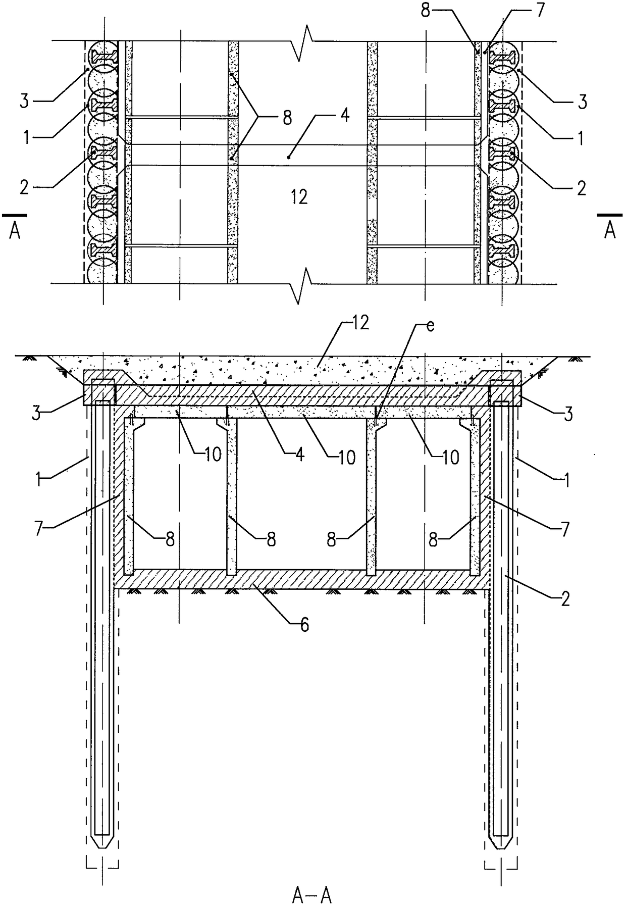
[0049] The construction sequence of the present invention's concrete implementation and each operation point are as follows:

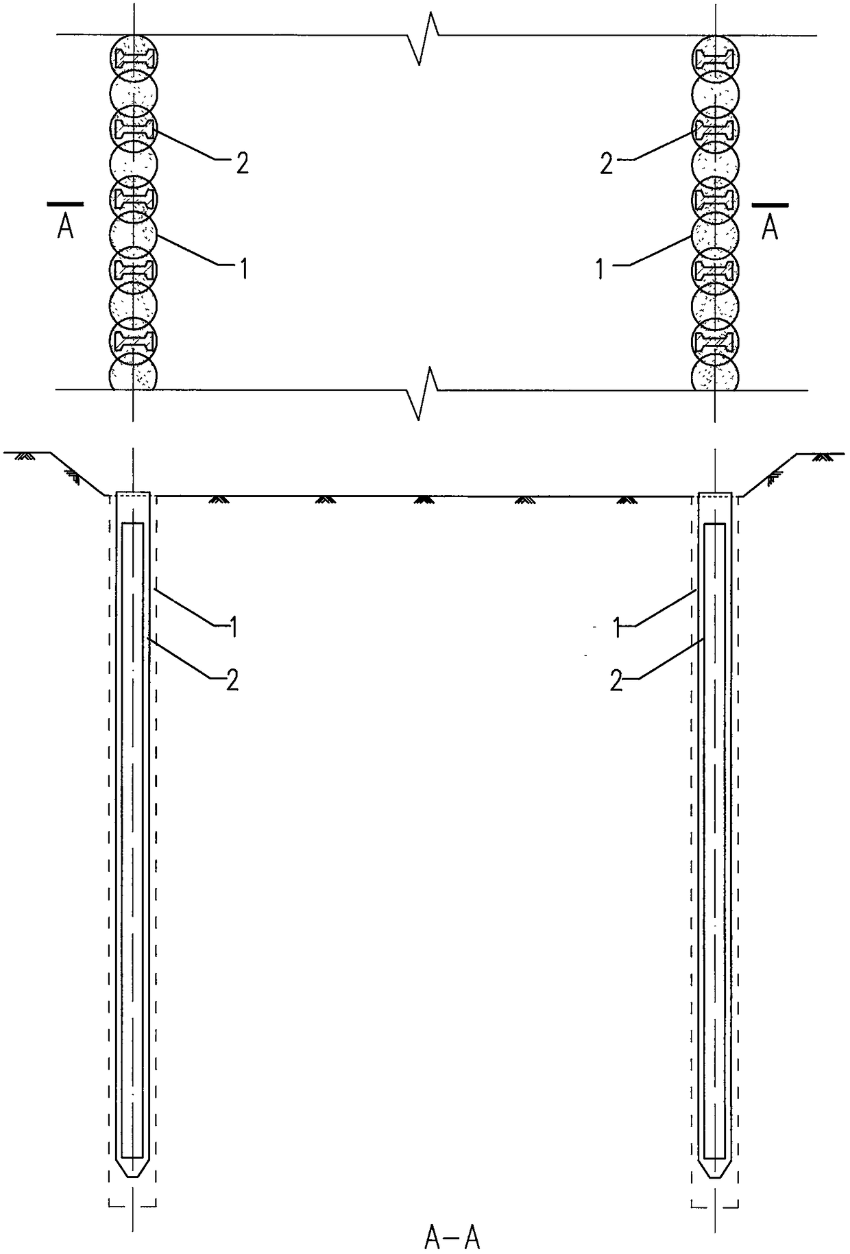
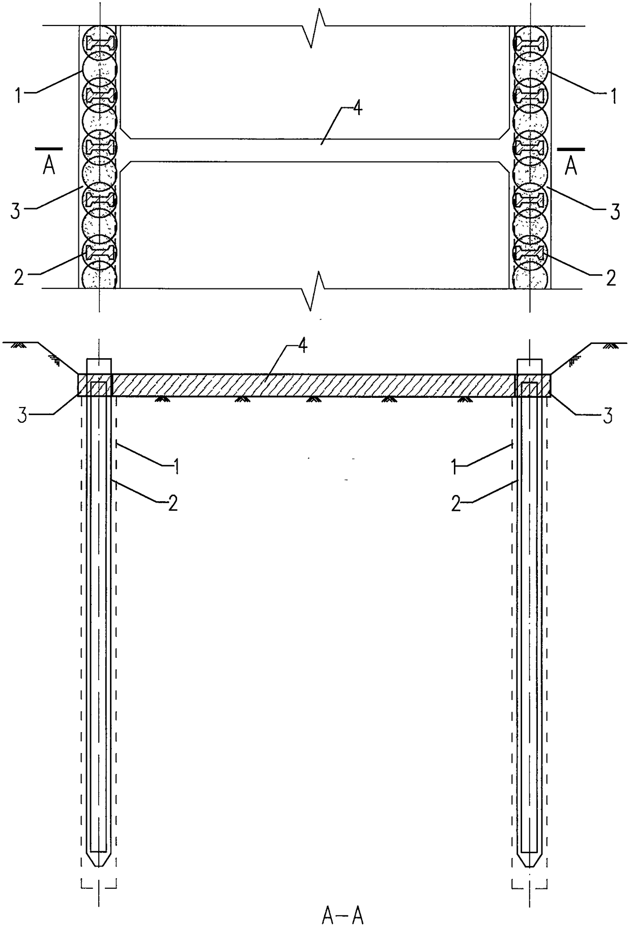
[0050] 1. First construct the retaining wall along both sides of the underground comprehensive pipe gallery. The retaining wall in the present invention adopts cement mixing pile 1 to implant prefabricated reinforced concrete I-shaped pile 2 to form (see attached Figure 2.1 ); the retaining pile is also used as an engineering anti-floating pile and an engineering pressure pile of the underground pipe gallery structure, and also serves as an external wall component of the underground pipe gallery, and shares the lateral water and soil pressure with other structures of the underground pipe gallery.

[0051] Steel plate a is pre-embedded on the prefabricated reinforced concrete H-shaped pile 2, which is used to weld the force-transmitting steel c; in the later stage, the method of digging out the pile reinforcement b can be used to connect the surrounding...


PUM


Abstract

In the underground comprehensive pipe rack construction process, cement-mixed soil is put into precast I-shaped piles which are internally provided with embedded parts, and then the precast I-shaped piles are used for forming an enclosure wall; and the embedded parts of the I-shaped piles are in rebar connection with a pipe rack bottom plate. When the pipe rack bottom pack is poured, outer liningwall rebars are pre-embedded, and specified guide grooves are reserved in the pipe rack bottom plate to be used for being connected with precast concrete plates; the precast concrete plates which arewell installed serve as a template for an outer lining wall and later-poured tope plate site-cast concrete, and then the enclosure piles, supporting beams and the pipe rack structure are connected into a whole; and therefore the stiffness of the pipe rack structure can be significantly strengthened, and the settlement and anti-floating problems of the pipe rack structure are solved. Compared witha traditional pipe rack construction process, according to the construction method, the constriction procedures can be simplified, the construction progress can be accelerated, the construction cost can be reduced, the influence on the environment is small, and the construction method accords with the state-sponsored low-carbon, environmental-protection and economical green development strategies.

Description

technical field [0001] The present invention is a new method for constructing urban comprehensive underground pipe gallery. It establishes a set of enclosure pile walls, pours the bottom plate, reserves guide grooves, connects with enclosure piles, and combines prefabricated reinforced concrete inner wall panels. , vertical slabs and top slabs, these prefabricated slabs are used as templates for cast-in-situ exterior wall linings and post-cast roof slabs, and integrally cast exterior wall linings, bottom slabs and top slabs are used to form a two-wall-in-one prefabricated slab splicing underground Construction method of integrated pipe gallery. Background technique [0002] At present, the commonly used construction method of urban underground comprehensive pipe gallery is: first set up protective piles (mainly steel sheet piles, bored piles, etc.) on both sides of the underground pipe gallery, and then excavate (cantilevered or supported) The form is the main form), and th...

Claims


Application Information

Patent Timeline
Patent Type & Authority Applications(China)
IPC IPC(8): E02D29/045
CPCE02D29/045E02D29/10
Inventor 严平
Owner HANGZHOU NANLIAN CIVIL ENG TECH
Why Eureka
Try Eureka