
Magnet ring based on micro motor rotor

A micro-motor and magnetic ring technology, applied in the field of micro-motors, can solve the problems of increasing motor vibration and noise, affecting motor performance, poor dynamic balance of magnetic rings, etc. Effect

Inactive Publication Date: 2018-11-13
XUZHOU XINLONG ELECTRONIC TECH CO LTD
View PDF0 Cites 2 Cited by
  • Summary
  • Abstract
  • Description
  • Claims
  • Application Information

AI Technical Summary

Problems solved by technology

The traditional multi-pole magnetic ring is made by bonding multiple magnetic segments, but it is difficult to process when making a small micro-motor. At the same time, it is difficult to make the magnetic pole angle accurately due to the splicing of multiple magnetic segments. It is difficult to achieve uniform quality of the entire magnetic ring, which makes the dynamic balance of the magnetic ring poor, increases the vibration and noise of the motor, and affects the performance of the motor

Method used


Image

  • Magnet ring based on micro motor rotor

Examples


Embodiment Construction

[0011] All features disclosed in this specification, or steps in all methods or processes disclosed, may be combined in any manner, except for mutually exclusive features and / or steps.

[0012] Any feature disclosed in this specification (including any appended claims, abstract and drawings), unless expressly stated otherwise, may be replaced by alternative features which are equivalent or serve a similar purpose. That is, unless expressly stated otherwise, each feature is one example only of a series of equivalent or similar features.

[0013] The specific implementation manners of the present invention will be described in detail below in conjunction with the drawings and embodiments.

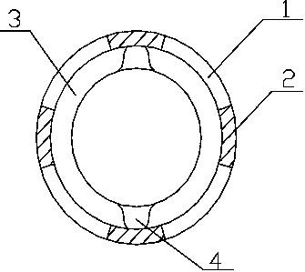
[0014] Such as figure 1 As shown, according to an embodiment of the present invention, this embodiment discloses a magnetic ring based on a micro-motor rotor, which includes a cylindrical magnetic ring body 1 and four pairs of arc-shaped magnetic segments 2, and the magnetic ring body It is...


PUM


Abstract

The invention discloses a magnet ring based on a micro motor rotor; the magnet ring comprises a magnet ring body and at least two pairs of arc-shaped magnet sections; the magnet ring body is an integrated structure formed by a magnetic material via injection moulding; the magnet sections are embedded in the magnet ring body, and evenly arranged in the magnet ring body with their polarities mutually inverted; the top surface, facing the inner wall of the magnet ring body, of the magnet ring body is connected with an end face, and two grooves are peripherally divided on the end face; the magnetring body is the integrated structure formed by a ferrite magnetic powder, a poly1, 9-subnonyl terephthalamide, a Polylaurolactam, a nylon 6 / clay nanocomposite and an oleic acid via injection moulding. The one time moulding multi-pole magnet ring can ensure the magnet ring concentricity and mass uniformity, and can simultaneously minimize the whole machine weight, so the motor can be higher in work efficiency, lower in noises, higher in an operation frequency, and large in a pull-out torque, thus fundamentally greatly improving the motor quality, and obtaining great technical progress.

Description

technical field [0001] The invention relates to the technical field of micro-motors, in particular to a magnetic ring based on micro-motor rotors. Background technique [0002] Micro motor, the full name of micro motor, refers to a motor with a diameter of less than 160mm or a rated power of less than 750W. Micromotors are often used in control systems or transmission mechanical loads to realize functions such as detection, analytical operation, amplification, execution or conversion of electromechanical signals or energy. The basic composition of the electromagnetic micromotor is similar to that of ordinary motors, including stators, rotors, armature windings, brushes and other components, but the structure is extremely compact. The traditional multi-pole magnetic ring is made by bonding multiple magnetic segments, but it is difficult to process when making a small micro-motor. At the same time, it is difficult to make the magnetic pole angle accurately due to the splicing...

Claims


Application Information

Patent Timeline
Patent Type & Authority Applications(China)
IPC IPC(8): H02K1/27H02K1/02
CPCH02K1/27H02K1/02H02K2213/03
Inventor 张伟
Owner XUZHOU XINLONG ELECTRONIC TECH CO LTD
Learn More