A low fluorescence bleaching confocal imaging method and system

An imaging method and confocal technology, applied in the field of low fluorescence bleaching confocal imaging method and system, can solve the problems of signal-to-noise ratio reduction, image loss, and reduction of effective fluorescent signal, etc., and achieve the effect of image quality reduction and efficient utilization

Active Publication Date: 2022-05-27
SUZHOU GUOKE MEDICAL TECH DEV CO LTD +1
View PDF9 Cites 0 Cited by
  • Summary
  • Abstract
  • Description
  • Claims
  • Application Information

AI Technical Summary

Problems solved by technology

[0003] At present, confocal microscopy imaging uses high numerical aperture objective lenses for focused imaging, and the formed high power density focused spot is likely to cause fluorescence bleaching of the sample.
In order to avoid fluorescence bleaching, you can simply reduce the optical power density, or reduce the illumination time to reduce the light dose and alleviate the problem of fluorescence bleaching, but this will reduce the effective fluorescence signal, resulting in loss of image details and a decrease in signal-to-noise ratio

Method used


Image

  • A low fluorescence bleaching confocal imaging method and system
  • A low fluorescence bleaching confocal imaging method and system
  • A low fluorescence bleaching confocal imaging method and system

Examples


Embodiment 1

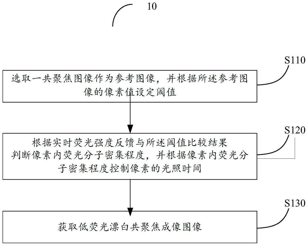
[0034] see figure 1 , is a flowchart of the steps of the low-fluorescence bleaching confocal imaging method 10 provided in Embodiment 1 of the present invention, including the following steps:

[0035] Step S110: Select a confocal image as a reference image, and set a threshold according to pixel values ​​of the reference image.

[0036] It can be understood that a standard confocal image is taken as a reference image before imaging with a low-fluorescence bleaching confocal imaging method (Controllable Light Exposure-Confocal Microscopy, CLE-CM), and the threshold is set for the reference image.

[0037] In some preferred embodiments, the above step S110 specifically includes the following steps:

[0038] Step S111: put the reference image in the

[0039] Step S112: put the reference image in the

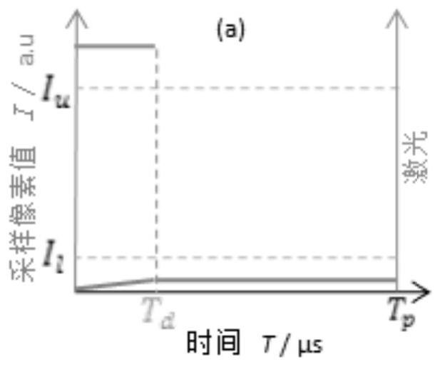
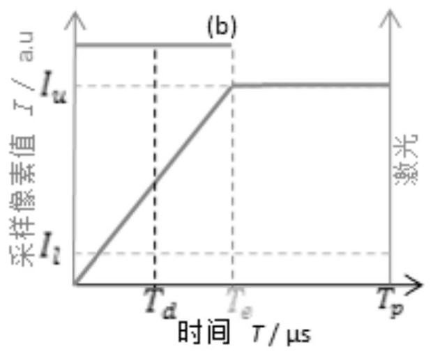
[0040] Step S120: Determine the density of fluorescent molecules in the pixel according to the comparison result of the real-time fluorescence intensity feedback and the...

Embodiment 2

[0053] see Figure 5 , is a schematic structural diagram of the low-fluorescence bleaching confocal imaging system 20 provided in Embodiment 2 of the present invention, including: a confocal imaging module 210 , an electronic control module 220 and a host computer module 230 . The confocal imaging module 210 includes a laser 211, a light intensity adjustment component 212, a high-speed optical switch 213, a dichroic mirror 214, a mirror 215, a relay lens 216, a tube lens 217, an objective lens 218, a displacement stage 219, and a detector 2110 , a pinhole 2111 and a detection lens 2112. The electronic control module 220 is electrically connected to the high-speed optical switch 213 . The host computer module 230 is electrically connected to the electronic control module 220 .

[0054] It can be understood that a confocal image can be obtained through the confocal imaging module 210 and used as a reference image; the host computer module 230 sets a threshold according to the ...


PUM


Abstract

The low fluorescence bleaching confocal imaging method provided by the present invention first selects a confocal image as a reference image, and sets a threshold according to the pixel value of the reference image, and then judges the fluorescence within the pixel according to the real-time fluorescence intensity feedback and the comparison result of the threshold Molecule density, and control the illumination time of the pixel according to the density of fluorescent molecules in the pixel, and finally obtain the low-fluorescence bleaching confocal imaging image. The low-fluorescence bleaching confocal imaging method and system provided by the present invention control the illumination of each object pixel Time, to use fluorescence information more efficiently, reduce fluorescence bleaching without sacrificing image quality, and can be applied to a variety of biological samples. In addition, the invention also provides a low fluorescence bleaching confocal imaging system.

Description

technical field [0001] The invention relates to the technical field of confocal microscopy, in particular to a low-fluorescence bleaching confocal imaging method and system. Background technique [0002] The three major factors of fluorescent bleaching are fluorescent molecules, chemical environment, and light dose. The bleaching reduction technology mainly starts from these three aspects, using special fluorescent dyes such as quantum dots, or changing the chemical environment of fluorescent molecules such as adding anti-bleaching agents. It is suitable for ordinary biological samples, and the method of improving the imaging technology to reduce the light dose is more suitable for ordinary biological samples. [0003] At present, confocal microscopy imaging is performed with a high numerical aperture objective lens for focusing imaging, and the resulting high power density focusing spot easily leads to fluorescence bleaching of the sample. In order to avoid fluorescence bl...

Claims


Application Information

Patent Timeline
Patent Type & Authority Patents(China)
IPC IPC(8): G01N21/64G02B21/00
CPCG02B21/0076G01N21/64G01N21/6458G02B21/0084G01N21/6408G02B21/365G01N2201/1242
Inventor 徐依雯张运海肖昀刘创
Owner SUZHOU GUOKE MEDICAL TECH DEV CO LTD
Why Eureka
Try Eureka