Peeling device and peeling method for cylindrical battery

A cylindrical battery and battery technology, which is applied in the use/repair of primary batteries, battery recycling, and repair/maintenance of secondary batteries, etc. Fast peeling speed, large-scale automated production, and improved recycling efficiency

Pending Publication Date: 2018-11-16
南京万舟发机电科技有限公司
0 Cites 1 Cited by

AI-Extracted Technical Summary

Problems solved by technology

However, in the existing technology, the processing is mostly performed b...

Abstract

The invention discloses a peeling device and a peeling method for a cylindrical battery. The peeling device has a structure which comprises a laser head, a downward-pressing transfer machine, a rollerpeeling unit, a battery material storage chamber, a battery conveyor belt, a cutting transfer machine and a laser head lift-drop unit, wherein the laser head and the laser head lift-drop unit are infixed connection; the cutting transfer machine and the downward-pressing transfer machine are arranged below the laser head; the battery conveyor belt is arranged below the left end of the cutting transfer machine; the roller peeling unit is arranged below the downward-pressing transfer machine; and the outlet end of the roller peeling unit is connected with the battery storage bin. The peeling device and the peeling method provided by the invention have the following advantages: 1) the speed of peeling is fast, so the efficiency of recovery is improved; 2) by adoption of a CO2 laser for cutting, a battery cell is not prone to be damaged; and 3) an outer peel and the battery cell can be automatically separated, so large-scale and automatic production can be realized.

Application Domain

Primary cell maintainance/servicingReclaiming serviceable parts +3

Technology Topic

Image

  • Peeling device and peeling method for cylindrical battery
  • Peeling device and peeling method for cylindrical battery
  • Peeling device and peeling method for cylindrical battery

Examples

  • Experimental program(1)

Example Embodiment

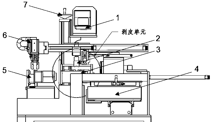
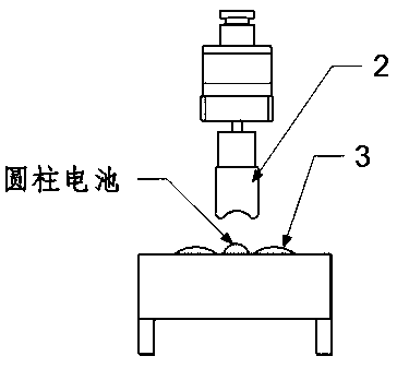
[0018] as attached figure 1 As shown, a cylindrical battery peeling device, its structure includes a laser head 1, a lower pressure transfer machine 2, a roller peeling device 3, a battery storage bin 4, a battery conveyor belt 5, a cutting transfer machine 6, a laser head Lifting device 7; wherein the laser head 1 is connected and fixed with the laser head lifting device 7, the cutting transfer machine 6 and the pressing transfer machine 2 are arranged under the laser head 1, and the battery conveyor is arranged under the left end of the cutting transfer machine 6 Belt 5; a roller peeling device 3 is provided below the lower pressure transfer machine 2, and the outlet end of the roller peeling device 3 is connected to the battery storage bin 4; the whole device is arranged on a horizontal frame.
[0019] The laser head lifting device 7 is installed on a longitudinal chute, and can vertically move up and down along the longitudinal chute to adjust the height position of the laser head 1 .
[0020] The cutting and transferring machine 6 and the pressing and transferring machine 2 are installed on a transverse chute, and can move horizontally along the transverse chute, and are responsible for moving the battery from the battery conveyor belt 5 to the laser head for cutting and moving to the roller Press up and down to peel the battery and remove the peeled battery to the battery storage bin.
[0021] as attached figure 2 As shown, the roller peeling device 3 includes two rollers with opposite rotation directions, the left roller rotates counterclockwise, and the right roller rotates clockwise.
[0022] The laser head of described laser head lifting device 7 adopts CO 2 Laser, the laser head controls the laser beam to move along the battery axis in the horizontal direction, so as to cut the plastic skin of the battery. The cutting position is as attached image 3 shown.
[0023] The peeling method of this device comprises the steps:
[0024] 1) The battery to be cut is transported by the battery conveyor belt 5 to the gripper of the cutting and transferring machine 6, and the cutting and transferring machine 6 grabs the battery and moves it under the laser head;
[0025] 2) Adjust the position of the laser head 1 through the laser head lifting device 7 so that its focus is on the plane where the axis of the plastic skin of the battery is located, start the laser head 1 to emit laser light, and the laser head controls the movement of the laser beam to cut the battery skin along the cutting axis. Use the friction between the battery and the roller to separate the skin from the battery core;
[0026] 3) The cut battery cores are put into the battery storage bin 4 on the lower right from the roller peeling device 3 by the lower pressure transfer machine 2 for further processing;
[0027] 4) When cutting a small-sized battery, move the lower pressure transfer machine 2 down against the surface of the battery, so that the battery is close to the roller to increase the friction force, thereby separating the outer skin and the battery core.
[0028] The invention does not damage the battery core, has fast peeling speed, is easy to form large-scale automatic production, can significantly improve the working efficiency of recycling battery cores in battery factories, and reduces recycling costs.

PUM

no PUM

Description & Claims & Application Information

We can also present the details of the Description, Claims and Application information to help users get a comprehensive understanding of the technical details of the patent, such as background art, summary of invention, brief description of drawings, description of embodiments, and other original content. On the other hand, users can also determine the specific scope of protection of the technology through the list of claims; as well as understand the changes in the life cycle of the technology with the presentation of the patent timeline. Login to view more.

Similar technology patents

Peeling device for garlic peeling

ActiveCN112273973APrevents blocking peelingFast peelingPeelersMechanical engineeringAllium sativum
Owner:SUZHOU LIHE INFORMATION TECH CO LTD

Intelligent fish peeling production line

ActiveCN114223703AFast peelingImprove production and processing efficiencyFish filletingFish skinningEngineeringManufacturing line
Owner:肇庆市振业水产冷冻有限公司

Automatic orange peeling machine

Owner:晴隆县小橙故事农业发展有限公司

Nut peeling machine convenient to move

InactiveCN112931889AFast peelingAdjust peeling depthHuskingHullingElectric machineryWater pipe
Owner:湖北万丈涯农业有限公司

Classification and recommendation of technical efficacy words

  • Improve recycling efficiency
  • Fast peeling

Nut peeling machine convenient to move

InactiveCN112931889AFast peelingAdjust peeling depthHuskingHullingElectric machineryWater pipe
Owner:湖北万丈涯农业有限公司

Peeling device for garlic peeling

ActiveCN112273973APrevents blocking peelingFast peelingPeelersMechanical engineeringAllium sativum
Owner:SUZHOU LIHE INFORMATION TECH CO LTD
Why Eureka
Try Eureka