
RF receiving circuit and RF receiver

A radio frequency receiving and circuit technology, applied in the field of communication, can solve the problems of large output power consumption and large chip area

Active Publication Date: 2018-11-16
SHENZHEN JOINTWAY IC DESIGN CO LTD
View PDF7 Cites 0 Cited by
  • Summary
  • Abstract
  • Description
  • Claims
  • Application Information

AI Technical Summary

Problems solved by technology

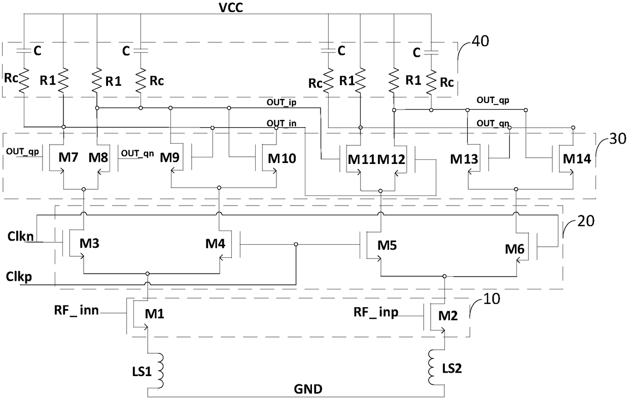
[0004] The purpose of the present invention is to provide a radio frequency receiving circuit, which realizes the amplification and mixing functions of radio frequency signals by multiplexing the SCL divider by two, and aims to solve the problems of large output power consumption and large chip area in the traditional technical solution The problem

Method used


Image

  • RF receiving circuit and RF receiver
  • RF receiving circuit and RF receiver
  • RF receiving circuit and RF receiver

Examples


Embodiment Construction

[0021] In order to make the objectives, technical solutions and advantages of the present invention clearer, the present invention will be further described in detail below with reference to the accompanying drawings and embodiments. It should be understood that the specific embodiments described herein are only used to explain the present invention, but not to limit the present invention.

[0022] figure 1 A schematic structural diagram of a radio frequency receiving circuit provided by a preferred embodiment of the present invention is shown. For the convenience of description, only the part related to this embodiment is shown, and the details are as follows:

[0023] A radio frequency receiving circuit includes: a tail current source 10 , a clock signal input unit 20 , a sample and hold unit 30 and a load unit 40 . It not only realizes the traditional quadrature signal generation function, but also amplifies and mixes the input RF signal, realizes the multiplexing of the d...


PUM


Abstract

The invention relates to the technical field of communication, in particular to an RF receiving circuit and an RF receiver. The RF receiving circuit comprises a tail current source, a clock signal input unit, a sampling and holding unit and a load unit, wherein the tail current source is multiplexed to access an RF signal and amplify the RF signal, so as to generate an RF current; the clock signalinput unit is connected with the tail current source, and is used for inputting a clock signal; the sampling and holding unit is connected with the clock signal input unit, and outputs an orthogonalsignal with the frequency being one-half clock frequency; the load unit is connected with the sampling and holding unit, the RF current flowing through the load unit is converted into a voltage and modulated by means of the orthogonal signal, and the load unit outputs an IF signal with the frequency being a difference of the RF signal frequency and the orthogonal signal frequency, thereby realizing frequency mixing. The RF receiving circuit achieves the traditional orthogonal signal generation function, can amplify and mix the input RF signal, and realizes the multiplexing of adivide-by-2 frequency dividing circuit.

Description

technical field [0001] The invention belongs to the technical field of communication, and in particular relates to a radio frequency receiving circuit and a radio frequency receiver. Background technique [0002] With the rapid development of modern communication systems, the communication industry has become an industry with a wide market audience, and the application of communication systems has penetrated into every corner of society. The RF receiver has also been widely used as a basic module in the communication system, and its performance (including power consumption / area / noise figure and linearity) improvement and potential development has also become a continuous and challenging research focus. [0003] In mobile communication, in order to prolong the standby time, reducing the power consumption of the receiver has always been a research hotspot. The traditional structure of the receiver, including low noise amplifier (LNA) / mixer (Mixer) / quadrature local oscilla...

Claims


Application Information

Patent Timeline
Patent Type & Authority Applications(China)
IPC IPC(8): H04B1/16H04B1/12
CPCH04B1/12H04B1/16H04B1/1607H03F3/45183H03F1/0205H03F3/193H03F2203/45444H03F2200/451H03F3/45192
Inventor 曾隆月阎跃鹏章松张常红王冬春
Owner SHENZHEN JOINTWAY IC DESIGN CO LTD
Learn More