
Quakeproof wafer grinder

A grinding machine and wafer technology, which is applied in grinding machine tools, grinding devices, grinding machine parts, etc., can solve the problems of poor wafer grinding stability, wafer skew, and reduced wafer grinding pass rate, etc. Chip removal time, increase yield, avoid excessive wafer processing effect

Inactive Publication Date: 2018-11-23
JIANGSU NEPES SEMICON
View PDF0 Cites 5 Cited by
  • Summary
  • Abstract
  • Description
  • Claims
  • Application Information

AI Technical Summary

Problems solved by technology

[0003] The object of the present invention is to provide an anti-vibration wafer grinder to solve the problem of poor stability of wafer grinding during the use of the wafer grinder proposed in the above background technology, which may easily cause deviation of the wafer during grinding. Slant, reducing the wafer grinding pass rate

Method used

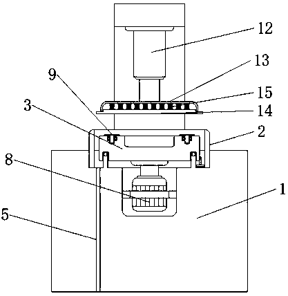
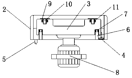
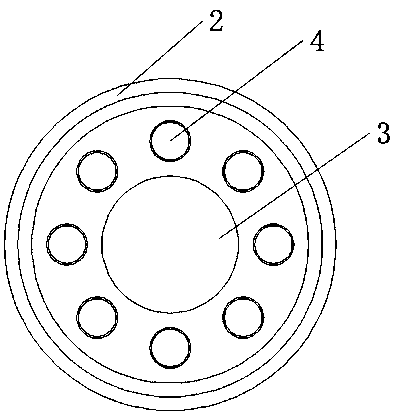

Image

  • Quakeproof wafer grinder
  • Quakeproof wafer grinder
  • Quakeproof wafer grinder

Examples


Embodiment 1

[0016] see figure 1 , figure 2 and image 3 , the present invention provides a technical solution: a shockproof wafer grinder, comprising a wafer grinder body 1, the upper surface of the wafer grinder body 1 is provided with a grinding seat 2, and the grinding seat 2 is fixed on the wafer by welding On the upper surface of the grinding machine body 1, the inside of the grinding seat 2 is provided with a runner 3, and the outer surface of the runner 3 is provided with a cleaning brush 4, and one end of the cleaning brush 4 is fixed on the outer surface of the runner 3 by welding, and the grinding seat 2 A debris discharge pipe 5 is opened inside of the wafer grinder body 1 , and the debris discharge pipe 5 runs through the interior of the wafer grinder body 1 and extends to the bottom of the wafer grinder body 1 .

[0017] In order to improve the balance of the rotation of the runner 3 and improve the precision of wafer processing, in this embodiment, preferably, the inner s...

Embodiment 2

[0022] see figure 1 , figure 2 and image 3 , the present invention provides a technical solution: a shockproof wafer grinder, comprising a wafer grinder body 1, a grinding seat 2 is arranged on the upper surface of the wafer grinder body 1, the grinding seat 2 and the wafer grinder body 1 Integral structure, the inside of the grinding seat 2 is provided with a runner 3, the outer surface of the runner 3 is provided with a cleaning brush 4, one end of the cleaning brush 4 is fixed on the outer surface of the runner 3 by welding, and the inside of the grinding seat 2 A debris discharge pipe 5 is opened, and the debris discharge pipe 5 runs through the interior of the wafer grinder body 1 and extends to the bottom of the wafer grinder body 1 .

[0023] In order to improve the balance of the rotation of the runner 3 and improve the precision of wafer processing, in this embodiment, preferably, the inner surface of the grinding base 2 is provided with a limiting ring 6, and one...


PUM


Abstract

The invention discloses a quakeproof wafer grinder. The quakeproof wafer grinder comprises a wafer grinder body; a grinding base is arranged on the upper surface of the wafer grinder body; the grinding base is fixedly arranged on the upper surface of the wafer grinder body; a rotary wheel is arranged in the grinding base; a cleaning brush is arranged on the outer surface of the rotary wheel; a slag emission pipe is arranged in the grinding base, penetrates through the inner part of the wafer grinder body and extends to the bottom of the wafer grinder body; a rotary motor, the rotary wheel, a grinding cover, a grinding wheel and a buffering spring are adopted, so that the rotary wheel is driven by the rotary motor; meanwhile, the grinding wheel clings to a wafer under the effect of the buffering spring; the wafer is enabled to rotate to be grinded; the wafer grinding efficiency is improved; the wafer grinding time is shortened; a supporting rod and a bearing are adopted at the lower part of each wafer groove, so that during a grinding process of wafers, the wafer grooves rotate around the bearings under the effect of grinding, and the grinding uniformity of the wafers is improved.

Description

technical field [0001] The invention belongs to the technical field of wafer grinding equipment, and in particular relates to an anti-shock wafer grinding machine. Background technique [0002] Wafer refers to the silicon wafer used in the production of silicon semiconductor integrated circuits. Because of its circular shape, it is called a wafer; it can be processed into various circuit element structures on the silicon wafer, and become an IC with specific electrical functions. product. The raw material of the wafer is silicon, and the surface of the earth's crust has an inexhaustible amount of silicon dioxide. The silicon dioxide ore is refined by an electric arc furnace, chlorinated with hydrochloric acid, and distilled to produce high-purity polysilicon, in which the wafers are 8 inches and 12 inches in size. During the use of the existing wafer grinder, the stability of wafer grinding is poor, which may easily cause the deflection of the wafer during the grinding pro...

Claims


Application Information

Patent Timeline
Patent Type & Authority Applications(China)
IPC IPC(8): B24B37/10B24B37/34B24B27/00B24B41/00B24B55/06B24B37/30
CPCB24B37/107B24B27/0015B24B37/30B24B37/34B24B41/007B24B55/06
Inventor 贾红星袁泉孙健陈业
Owner JIANGSU NEPES SEMICON
Learn More