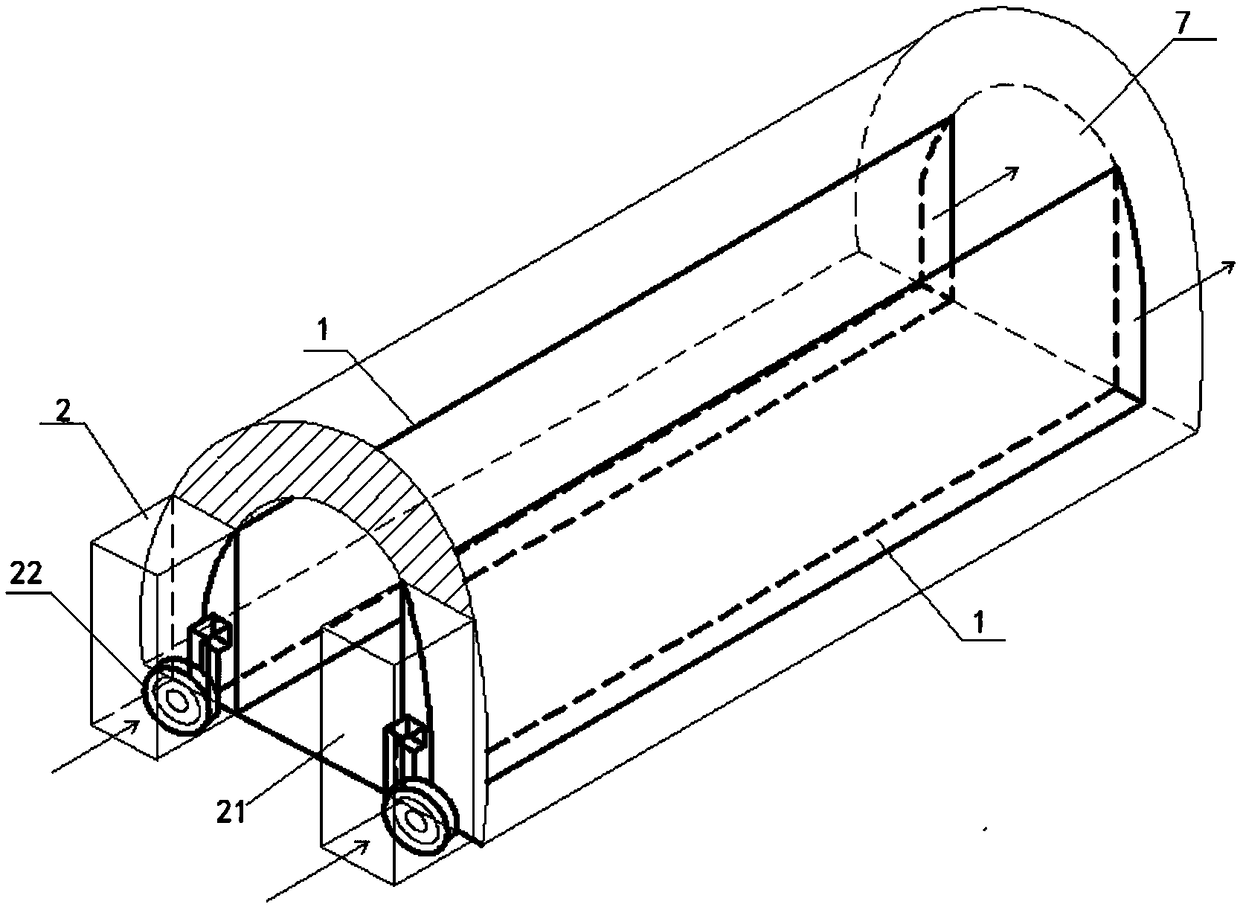
Air supply system for achieving natural energy dehumidification by using underground tunnel wall surface
An air supply system and underground tunnel technology, which is applied in the ventilation of mines/tunnels, mining equipment, and earth-moving drilling, etc., can solve the problems of fogging of workshops, obstacles of underground traffic tunnels, affecting the health and work efficiency of workers, etc. To achieve the effect of reducing load and reducing air moisture content
- Summary
- Abstract
- Description
- Claims
- Application Information
AI Technical Summary
Problems solved by technology
Method used
Image

Examples
Embodiment 1
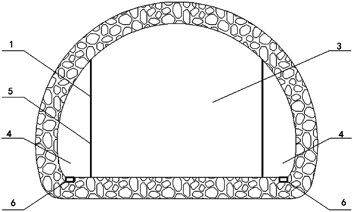
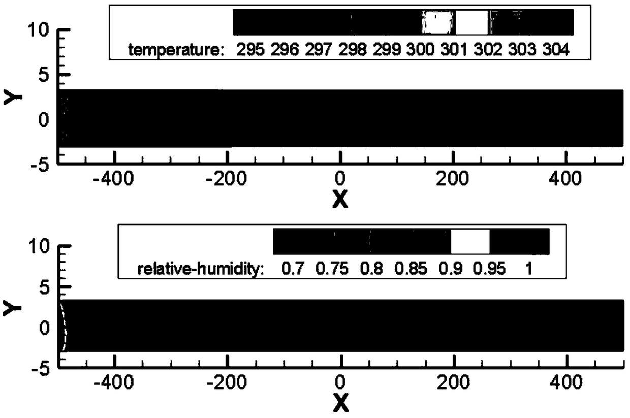
[0030] According to the actual situation, the size of the underground tunnel is 1000000(x)×8000(y)×8000(z)(mm 3 ) numerical calculation model, the partition plate is arranged on both sides 500mm away from the side wall, and arranged along the x-axis from the entrance to the end of the tunnel. For summer working conditions, the temperature of all walls inside the underground tunnel is 295K, and the wall surface roughness is 0.1; the temperature of the air supply air at the entrance of the tunnel is 305K, the relative humidity is 70%, and the air supply speed is 8m / s; the material of the partition plate is stainless steel plate And set the heat insulation layer, the heat flux is 0W / m 2 .
[0031] In order to verify the heat exchange effect between the air in the air supply duct and the cave wall in this embodiment, the average turbulence energy model, namely the standard k-ε model, is used to solve the equations.
[0032] image 3 It is the air temperature and relative humidi...
Embodiment 2
[0036] Establish the same numerical calculation model as in Example 1, changing the wall roughness to 0.2. The enthalpy value of the air from the inlet to the end of the air duct is reduced by 22.62kJ / kg, and the moisture content is reduced by 4.72g / kg. Compared with Example 1, the changes of enthalpy and moisture content of the inlet and end air are the same, but the heat exchange efficiency is different. For the comparison results, see Figure 5 .
Embodiment 3
[0038] Establish the same numerical calculation model as in Example 1, changing the wall roughness to 0.3. The enthalpy value of the air from the inlet to the end of the air duct is reduced by 22.62kJ / kg, and the moisture content is reduced by 4.72g / kg. Compared with Example 1, the changes of enthalpy and moisture content of the inlet and end air are the same, but the heat exchange efficiency is different. For the comparison results, see Image 6 .
[0039]The environmental control goal of underground tunnels in summer is to use natural energy to achieve cooling and dehumidification to save high-grade energy. Embodiment 1, Embodiment 2 and Embodiment 3 are respectively the air inlet effect simulation under different roughness working conditions of the wall surface of the air inlet tunnel, and it can be found from the analysis of the results that using the air inlet tunnel of the present invention to supply air compared with the traditional tunnel The cooling and dehumidifica...
PUM
 Abstract
Description
Claims
Application Information