Multi-energy complementary integrated power generation system
A power generation system and air technology, applied in the field of multi-energy complementary comprehensive power generation systems, can solve the problems of low efficiency, high operating costs, and unstable output of power generation systems, and achieve the effects of saving consumption, reducing investment costs, and reducing utilization
- Summary
- Abstract
- Description
- Claims
- Application Information
AI Technical Summary
Problems solved by technology
Method used
Image
Examples
Embodiment 1
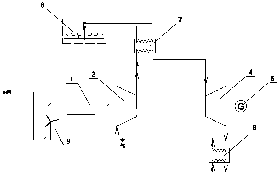
[0028] Such as figure 1 As shown, it is a schematic structural diagram of the unconnected burner of the present invention, including: an air compressor 2, a photothermal heat storage device 6, a photothermal-air heat exchanger 7, an air expander 4, a generator 5 and a power supply system.
[0029] The power supply system includes: an electric energy storage device 1, a wind power generation system 9 and three-phase AC mains, the wind power generation system 9 and the three-phase AC mains are electrically connected to the electric energy storage inlet of the electric energy storage device 1 respectively through a switch, and the power storage device 1 The electric energy output port is connected with the electric motor of the air compressor through a switch, and is used for supplying power to the electric motor of the air compressor 2 .
[0030] The air expander 4 and the generator 5 adopt a coaxial design structure. When the high temperature and high pressure air drives the ai...
Embodiment 2
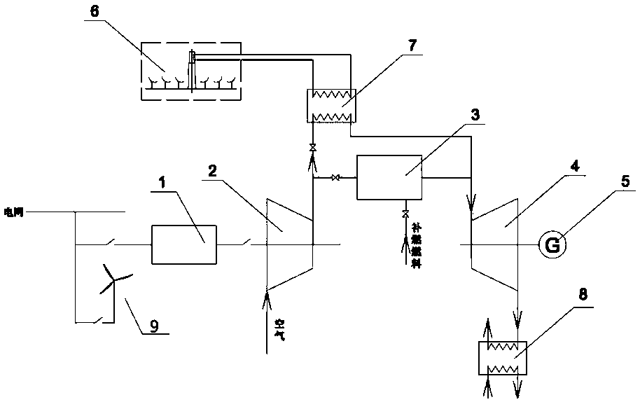
[0037] Such as figure 2 As shown, the difference between the second embodiment and the first embodiment is that a burner 3 is also connected between the air compressor 2 and the air expander 4, and the air inlet of the burner 3 passes through a one-way air valve. It is connected with the exhaust port of the air compressor 2, and the gas discharge port of the burner 3 is connected with the air inlet of the air expander 4 through the second check valve, and the fuel supply port of the burner 3 is connected with the fuel supply system .
[0038] Part of the high-pressure air output by the air compressor 2 is output to the photothermal-air heat exchanger 7 to exchange heat with the heat storage medium, and the other part is output to the burner 3 to be mixed with the fuel in the burner 3 to generate high-temperature gas; The high-temperature gas output from the burner 3 is mixed with the high-temperature and high-pressure air output from the photothermal-air heat exchanger 7, an...
Embodiment 3
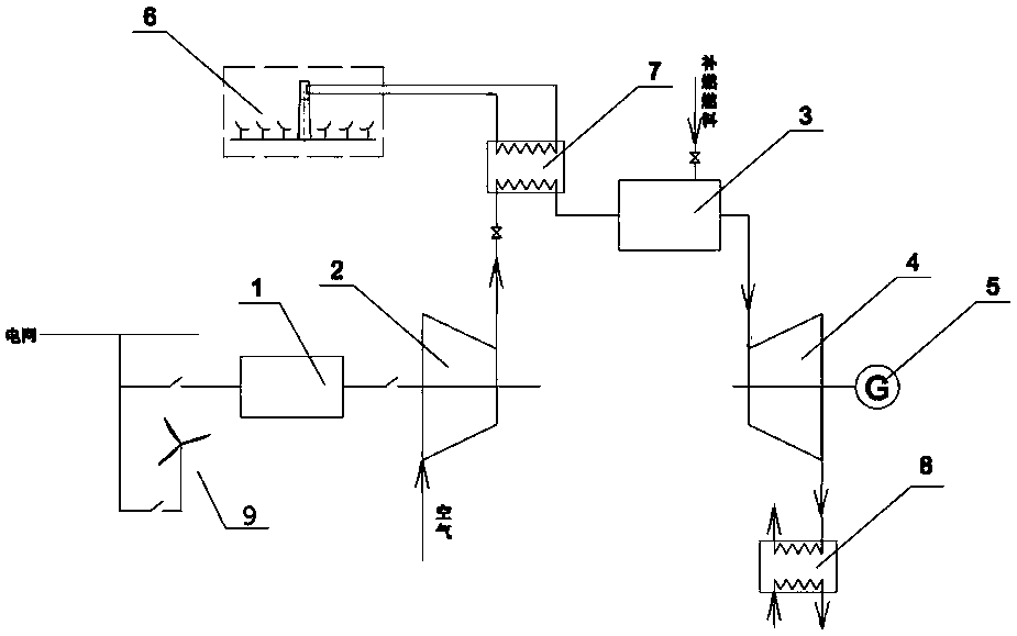
[0041] Such as image 3 As shown, the difference between the third embodiment and the first embodiment is that a burner 3 is connected between the photothermal-air heat exchanger 7 and the air expander 4, and the air inlet of the burner 3 is connected with the photothermal - The outlet of the cold medium pipeline of the air heat exchanger 7 is connected, the gas discharge port of the burner 3 is connected with the air inlet of the air expander 4, and the fuel supply port of the burner 3 is connected to the fuel supply system.
[0042] The high-pressure air output from the air compressor 2 is output to the photothermal-air heat exchanger 7 to exchange heat with the heat storage medium, and the high-temperature and high-pressure air output from the photothermal-air heat exchanger 7 is input to the burner 3 to communicate with the heat in the burner 3 The fuels are mixed and burned to generate high-temperature and high-pressure mixed gas, which is output to the air expander 4 to ...
PUM
 Abstract
Description
Claims
Application Information
 - R&D
- Intellectual Property
- Life Sciences
- Materials
- Tech Scout
- Unparalleled Data Quality
- Higher Quality Content
- 60% Fewer Hallucinations
Browse by: Latest US Patents, China's latest patents, Technical Efficacy Thesaurus, Application Domain, Technology Topic, Popular Technical Reports.
© 2025 PatSnap. All rights reserved.Legal|Privacy policy|Modern Slavery Act Transparency Statement|Sitemap|About US| Contact US: help@patsnap.com


