
Electrothermal composite material with three-dimensional filling structure

A composite material and electric heating technology, applied in the field of textile processing, can solve the problems of slowing down the heating speed, emission, poor impact resistance of the electric heating sheet, etc., and achieve the effects of fast weaving speed, good integrity and high impact resistance.

Inactive Publication Date: 2018-11-23
QUANZHOU NORMAL UNIV
View PDF9 Cites 4 Cited by
  • Summary
  • Abstract
  • Description
  • Claims
  • Application Information

AI Technical Summary

Problems solved by technology

[0002] At present, the existing electric heating plates are generally composed of multi-layer heating materials, and the two sides of the electric heating sheet are directly compounded with resin layers to obtain electric heating materials with certain insulation and waterproof properties, and then the electric heating materials are composited on boards such as wood or stone. In general, the above structure has the following disadvantages: Since both sides of the electric heating sheet will generate heat dissipation, the electric heating sheet laid on the side facing the ground will heat the ground, resulting in unnecessary energy consumption and slowing down the heating speed
In addition, because the electric heating sheet is directly compounded in the resin layer without strengthening treatment, the impact resistance of the electric heating sheet is poor, and delamination is easy to occur between the multi-layer heating materials.

Method used


Image

  • Electrothermal composite material with three-dimensional filling structure

Examples


Embodiment Construction

[0028] In order to further explain the technical solution of the present invention, the present invention will be described in detail below through specific examples.

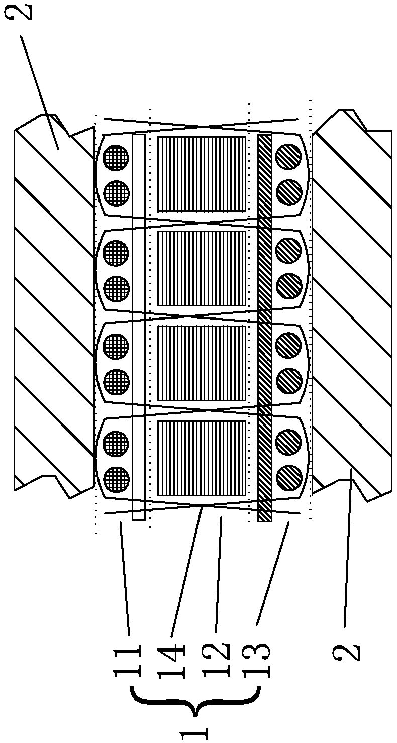
[0029] Such as figure 1 The three-dimensional filling structure electrothermal composite material shown includes a fabric layer 1 with a three-dimensional fabric structure and a resin layer 2 compounded on the above fabric layer, and the fabric layer 1 faces the ground when it is placed flat on the ground under normal use. One side is the lower side, and the side of the fabric layer 1 facing away from the ground is the upper side. The fabric layer 1 includes an electric heating layer 11, a heat insulating layer 12, a support layer 13 and a binding yarn 14, and the electric heating layer 11, heat insulation layer 12 and support The layers 13 are stacked in parallel in the vertical direction, the heat insulation layer 12 is located below the electric heating layer 11, the supporting layer 13 is arranged below the...


PUM

PropertyMeasurementUnit
diameteraaaaaaaaaa
diameteraaaaaaaaaa
lengthaaaaaaaaaa

Abstract

The invention discloses an electrothermal composite material with a three-dimensional filling structure. The electrothermal composite material comprises a fabric layer with a three-dimensional fabricstructure and two resin layers composited on the fabric layer; the fabric layer comprises an electrothermal layer, a thermal insulation layer, a support layer and binder yarn, wherein the electrothermal layer, the thermal insulation layer and the support layer are connected through the binder yarn, and the binder yarn is arranged on a protection layer, the electrothermal layer, the thermal insulation layer and the support layer in a penetrating mode; a conducting material is welded to the electrothermal layer, and the electrothermal layer is a fabric layer formed by weaving basalt fiber-coatedcopper wires which serve as warp yarn and weft yarn; the thermal insulation layer is a phenolic resin foaming material layer; the support layer is a fabric layer formed by weaving glass fiber; the binder yarn is glass fiber; and the two resin layers are composited on the two side faces of the fabric layer respectively and are unsaturated polyester resin layers. The electerothermal composite material has the advantages of being good in structure integrity, high in heating speed and heating efficiency and resistant to impact.

Description

technical field [0001] The invention relates to the technical field of textile processing, in particular to a three-dimensional filling structure electrothermal composite material. Background technique [0002] At present, the existing electric heating plates are generally composed of multi-layer heating materials, and the two sides of the electric heating sheet are directly compounded with resin layers to obtain electric heating materials with certain insulation and waterproof properties, and then the electric heating materials are composited on boards such as wood or stone. In general, the above structure has the following disadvantages: Since both sides of the electric heating sheet will generate heat dissipation, the electric heating sheet laid on the side facing the ground will heat the ground, resulting in unnecessary energy consumption and slowing down the heating speed. In addition, since the electric heating sheet is directly compounded in the resin layer without st...

Claims


Application Information

Patent Timeline
Patent Type & Authority Applications(China)
IPC IPC(8): H05B3/34B29B11/14B29C70/42B29C70/88D03D1/00D03D13/00D03D15/00D03D15/02D03D25/00D03D15/242D03D15/25D03D15/267D03D15/47D03D15/533
CPCH05B3/345D03D1/0088D03D13/008D03D25/005B29B11/14B29C70/42B29C70/882H05B2203/017D03D15/247D03D15/267D03D15/593B29C49/071B29C2949/0715
Inventor 冯丽丽许福军邱夷平张初阳
Owner QUANZHOU NORMAL UNIV
Learn More