Device for producing graphene

A graphene and box technology, applied in the field of graphene production equipment, can solve problems such as easy generation of dust, unstable discharge, and health hazards of personnel, so as to ensure balance and stability, good production quality, and avoid injuries Effect

Inactive Publication Date: 2018-11-27
福建科华中盈新材料有限公司
View PDF0 Cites 2 Cited by
  • Summary
  • Abstract
  • Description
  • Claims
  • Application Information

AI Technical Summary

Problems solved by technology

[0003] During the production of graphene, the reactor needs to be cooled, and the appropriate temperature provides the necessary conditions for the reaction of the materials in the reactor. The existing production equipment uses electric cooling during the cooling process, and long-term use will easily cause energy waste; the existing Most of the production equipment in the country uses manual labor when feeding materials. During the feeding process, manual labor cannot guarantee the uniformity of the materials being fed, which will cause adverse effects such as unstable discharge and low output, making it difficult to achieve large-scale mass production; the existing The quality of graphene produced by the production equipment is not good, and the produced impurities contain more, which affects the sales of graphene; the existing production equipment is prone to dust during the production process, and the labor intensity of the staff is high, which is harmful to the health of the personnel. the harm of

Method used


Image

  • Device for producing graphene
  • Device for producing graphene
  • Device for producing graphene

Examples


Embodiment Construction

[0015] The following will clearly and completely describe the technical solutions in the embodiments of the present invention with reference to the accompanying drawings in the embodiments of the present invention. Obviously, the described embodiments are only some, not all, embodiments of the present invention. Based on the embodiments of the present invention, all other embodiments obtained by persons of ordinary skill in the art without making creative efforts belong to the protection scope of the present invention.

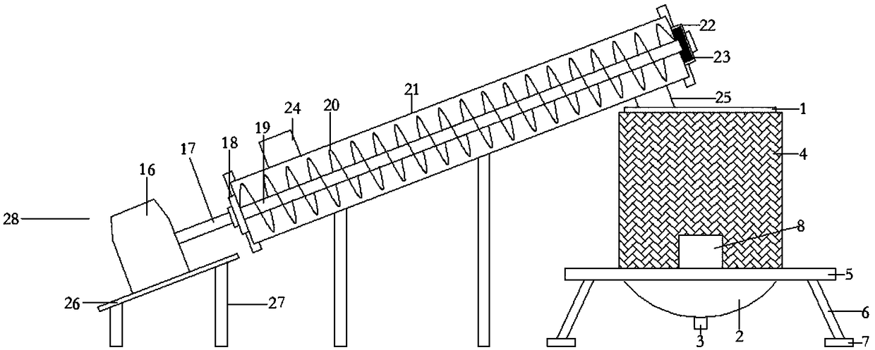
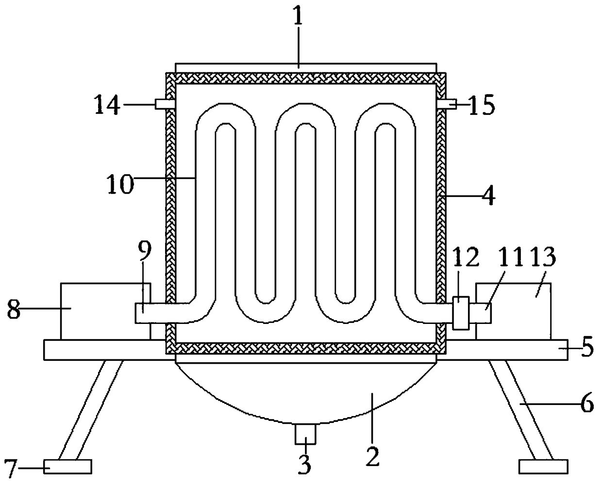
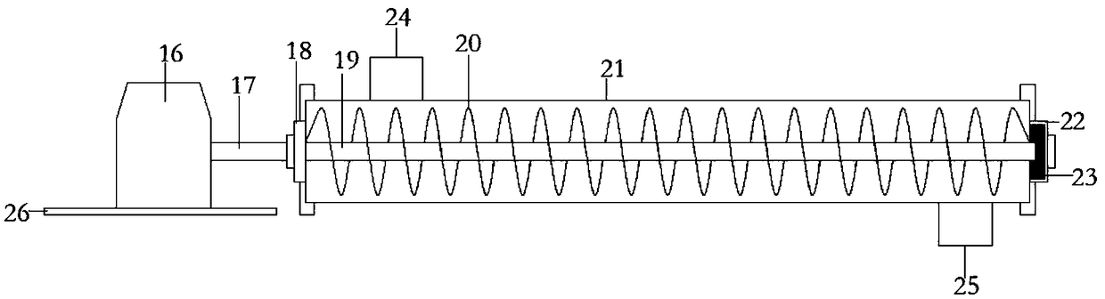
[0016] see Figure 1~3 , in an embodiment of the present invention, a device for graphene production, comprising a box body 1, a lower box body 2, a discharge port 3, an insulation layer 4, a support plate 5, a support rod 6, a support foot 7, a recovery water tank 8, Water outlet 9, water pipe 10, water inlet 11, water accelerator 12, main water tank 13, air inlet 14, air outlet 15, motor 16, output shaft 17, left flange 18, main shaft 19, helical blade 20, o...


PUM


Abstract

The invention discloses a device for producing graphene. A discharging opening is formed in the center of a lower box body, a heat preservation layer is arranged on the outer surface of the box body,support rods are arranged on the lower end face of a support plate, support legs are arranged at the lower ends of the support rods, and a recycling water tank and a main water tank are arranged at the upper end of the support plate; a water outlet of a water pipe is connected to the right end of the recycling water tank, a water inlet of the water pipe is connected to the left end of the main water tank, a water flow accelerator is arranged at the portion, of the end of the water inlet, of the water pipe, an air inlet is formed in the upper left end of the box body, an air outlet is formed inthe upper right end of the box body, and a feeding device is arranged at the left side of the box body; an output shaft is arranged at the right end of a motor, a left flange is arranged at the rightend of the output shaft, the left flange and a right flange sleeve the two ends of an outer cylinder, the output shaft stretches into the outer cylinder and is connected with the left end of a main shaft, and spiral blades are arranged on the main shaft; the right end of the main shaft is arranged in a tail bearing, the tail bearing is arranged in the right flange, a feed inlet is formed in the upper left end of the outer cylinder, a feed outlet is formed in the lower right end of the outer cylinder, a transverse plate is arranged on the lower end face of the motor, and support pillars are arranged at the lower ends of the transverse plate and the outer cylinder.

Description

technical field [0001] The invention relates to the technical field of graphene production equipment, in particular to a graphene production device. Background technique [0002] Graphene is a carbon atom with sp 2 Hybrid orbitals form a hexagonal two-dimensional carbon nanomaterial with a honeycomb lattice. Graphene has excellent optical, electrical, and mechanical properties, and has important applications in materials science, micro-nano processing, energy, biomedicine, and drug delivery. Foreground, it is considered to be a revolutionary material in the future. The research upsurge of graphene has also attracted the interest of material preparation research at home and abroad. The preparation methods of graphene materials have been reported: mechanical exfoliation method, chemical oxidation method, crystal epitaxy Growth method, chemical vapor deposition method, organic synthesis method and carbon nanotube stripping method, etc. [0003] During the production of graphe...

Claims


Application Information

Patent Timeline
Patent Type & Authority Applications(China)
IPC IPC(8): C01B32/184
CPCC01B32/184
Inventor 许怒涛
Owner 福建科华中盈新材料有限公司
Why Eureka
Try Eureka