White corundum block waste heat utilization system

A white corundum and waste heat technology, applied in the field of white corundum block waste heat utilization system, can solve problems such as non-compliance and unfavorable health of staff

Pending Publication Date: 2018-11-30
河南玉发磨料有限公司
View PDF18 Cites 10 Cited by
  • Summary
  • Abstract
  • Description
  • Claims
  • Application Information

AI Technical Summary

Problems solved by technology

[0002] Usually, the smelted white corundum needs to be put into the cooling pool for cooling, and a lot of waste heat will be generated during the cooling process. There is no preheating recovery technology in the existing technology, and a lot of heat is emitted, especially in summer. It will make the working environment extremely stuffy, which is not good for the health of the staff, and does not conform to the concept of energy saving, emission reduction and low-carbon production advocated by the country at present.

Method used


Image

  • White corundum block waste heat utilization system
  • White corundum block waste heat utilization system
  • White corundum block waste heat utilization system

Examples


Embodiment Construction

[0018] The technical solution of the present invention will be further described below in conjunction with the accompanying drawings.

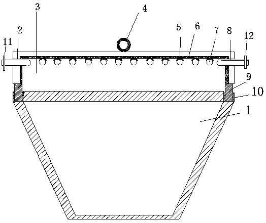
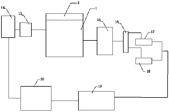
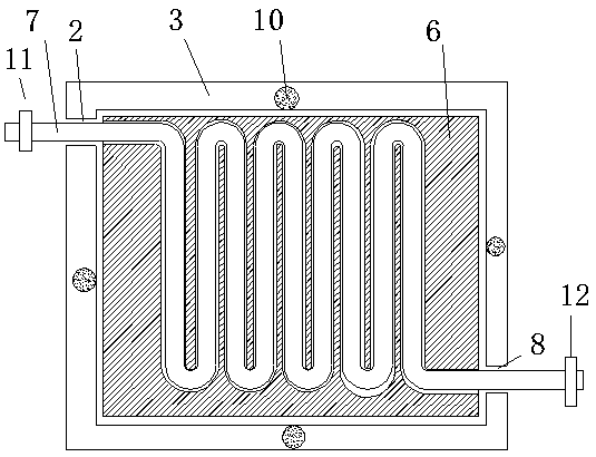
[0019] like figure 1 - Shown in 4: a white corundum block waste heat utilization system, including a cooling pool 1, the cooling pool 1 is a quadrangular pyramid structure with a large upper part and a smaller lower part, and a heat collecting cover is arranged above the cooling pool 1 3. The heat collecting cover 3 is a square frame structure, and the upper left side of the heat collecting cover 3 is provided with a pipe hole A2 for installing a quick heat pipe 7, and the fast heat water pipe 7 penetrates through the pipe hole A2 In the heat collecting cover 3, the part of the fast heat water pipe 7 placed in the heat collecting cover 3 is coiled on the upper wall of the heat collecting cover 3, and is led out through the pipe hole B8 provided under the right side of the heat collecting cover 3; The inner upper wall and the inner side wall o...


PUM


Abstract

A white corundum block waste heat utilization system comprises a cooling tank. A heat collecting cover is arranged above the cooling tank, and a pipe hole A for installing a rapid heating water guidepipe is formed in the upper portion of the left side of the heat collecting tank. The rapid heating water guide pipe runs through the pipe hole A into a cooling cover, is placed in a furnace cover andpartially wound on the upper wall of the heat collecting cover, and is led out through a pipe hole B in the right side of the heat collecting tank. The heat collecting cover is internally provided with a heat conducting layer, and the surface of the heat conducting layer on the upper wall of the heat collecting cover is provided with an arc-shaped heat conducting sheet in the shape of a coil. Therapid heating water guide pipe is coiled in the arc-shaped heat conducting sheet, and the lower end of the heat collecting cover is respectively provided with a heat conducting column. The upper endof the heat conducting column is connected with the heat conducting layer on the inner side wall of the heat collecting cover, and the lower end of the heat conducting column is matched with a heat dissipating groove formed in an opening at the upper end of the cooling tank in use. A gap is formed between the lower end edge of the heat collecting cover and the upper end edge of the cooling tank. The rapid heating water guide pipe at the pipe hole A is connected with a pressurizing water pump connected with a cold water storage tank. The rapid heating water guide pipe led out from the pipe holeB is connected with a hot water storage tank.

Description

technical field [0001] The invention belongs to the technical field of industrial waste heat reuse, and in particular relates to a white corundum block waste heat utilization system. Background technique [0002] Usually, the smelted white corundum needs to be put into the cooling pool for cooling, and a lot of waste heat will be generated during the cooling process. There is no preheating recovery technology in the existing technology, and a lot of heat is emitted, especially in summer. It will make the working environment extremely stuffy, which is not good for the health of the staff, and does not conform to the current concept of energy saving, emission reduction and low-carbon production advocated by the state. Contents of the invention [0003] The purpose of the present invention is to overcome the deficiencies of the prior art, and provide a waste heat utilization system with simple structure, easy implementation, and advanced concept, which can improve the working...

Claims


Application Information

Patent Timeline
Patent Type & Authority Applications(China)
IPC IPC(8): F27D17/00
CPCF27D17/004F27D2017/006Y02P10/25
Inventor 袁全忠
Owner 河南玉发磨料有限公司
Why Eureka
Try Eureka