Organic electroluminescent material and organic electroluminescent device thereof

A technology of electroluminescent materials and electroluminescent devices, which is applied in the direction of luminescent materials, electric solid devices, electrical components, etc., can solve the problems of limited materials and unsatisfactory functions, and achieve good film-forming properties, high glass transition temperature, The effect of lowering the driving voltage

Inactive Publication Date: 2018-12-07
CHANGCHUN HYPERIONS TECH CO LTD
View PDF0 Cites 13 Cited by
  • Summary
  • Abstract
  • Description
  • Claims
  • Application Information

AI Technical Summary

Problems solved by technology

However, the materials currently used for the second hole transport layer are very l

Method used


Image

  • Organic electroluminescent material and organic electroluminescent device thereof
  • Organic electroluminescent material and organic electroluminescent device thereof
  • Organic electroluminescent material and organic electroluminescent device thereof

Examples


Embodiment Construction

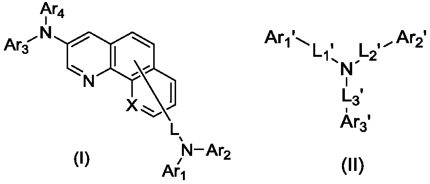
[0037] The present invention firstly provides a kind of organic electroluminescence material, and this material comprises the structure shown in general formula (I) and general formula (II):

[0038]

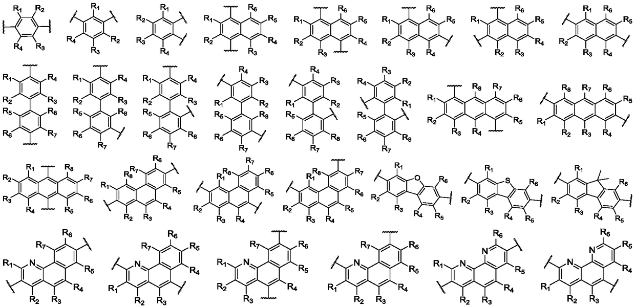
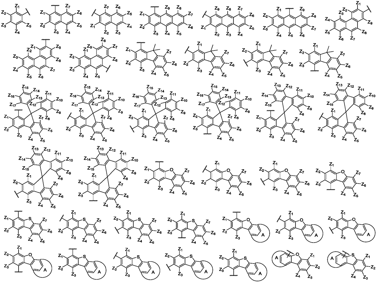
[0039] Wherein, X is selected from C or N; L, L 1 ’, L 2 ’, L 3 'Independently selected from single bond, C6~C30 substituted or unsubstituted divalent aryl, C3~C30 substituted or unsubstituted divalent heteroaryl; Ar 1 、Ar 2 、Ar 3 、Ar 4 independently selected from C6-C60 substituted or unsubstituted aryl, C3-C60 substituted or unsubstituted heteroaryl, or Ar 1 with Ar 2 can be connected to each other to form a nitrogen-containing five-membered heterocycle, or Ar 3 with Ar 4 Can be connected to each other to form a nitrogen-containing five-membered heterocycle; Ar 1 'C25-C60 substituted or unsubstituted 9,9'-spirobifluorenyl; Ar 2 'C16-C30 substituted or unsubstituted dibenzofuryl, C16-C30 substituted or unsubstituted dibenzothienyl; Ar 3 'is selected from C6-C60 su...


PUM


Abstract

The invention provides an organic electroluminescent material and an organic electroluminescent device thereof, and relates to the technical field of organic photoelectric materials. The organic electroluminescent material is a mixture of two compounds. The highest occupied molecular orbital energy level, hole mobility and glass transition temperature of the organic electroluminescent material arevery high, so that the organic electroluminescent material has very good solubility, amorphous film formation, stability and fluorescence properties. As first and second hole transport layers, the organic electroluminescent material can be applied in OLED devices to significantly improve the luminescence efficiency, color purity and service life of the OLED devices, can also reduce the driving voltage of the OLED devices, and is an OLED material with excellent performance.

Description

technical field [0001] The invention relates to the technical field of organic photoelectric materials, in particular to an organic electroluminescent material and an organic electroluminescent device. Background technique [0002] Organic Light-Emitting Diode (OLED), also known as organic electric laser display, is a double-injection light-emitting device. The device structure consists of an anode, a cathode, and more than one organic thin film layer between the anode and the cathode. . Its light-emitting mechanism is: apply a voltage between the anode and the cathode, electrons are injected from the cathode side, holes are injected from the anode side, the two combine to form excitons in the light-emitting layer, and the excitons return from the excited state to The ground state, thereby emitting light, realizes the direct conversion of electrical energy into light energy of organic semiconductor material molecules. [0003] The hole transport layer is currently a resear...

Claims


Application Information

Patent Timeline
IPC IPC(8): C07D221/10C07D307/77C07D307/91C07D333/50C07D401/04C07D401/10C07D405/12C07D409/12C07D409/14C07D471/04C09K11/06H01L51/54
CPCC09K11/06C07D221/10C07D307/77C07D307/91C07D333/50C07D401/04C07D401/10C07D405/12C07D409/12C07D409/14C07D471/04C09K2211/1092C09K2211/1088C09K2211/1011C09K2211/1014C09K2211/1029H10K85/624H10K85/636H10K85/626H10K85/633H10K85/615H10K85/6576H10K85/6574H10K85/6572
Inventor 周雯庭蔡辉
Owner CHANGCHUN HYPERIONS TECH CO LTD
Why Eureka
Try Eureka