Dry quenching furnace with water-cooling lifting frame and ring-shaped pre-storage chamber and working method of dry quenching furnace

A technology of pre-storage chamber and dry quenching furnace, applied in the field of dry quenching furnace, which can solve the problems of increasing the flow rate of circulating gas, blockage of chute opening 1-9, affecting the structural stability of inner ring wall 1-6, etc., to achieve uniform distribution and segregation The effect of reducing

Pending Publication Date: 2018-12-07
ACRE COKING & REFRACTORY ENG CONSULTING CORP DALIAN MCC
View PDF0 Cites 0 Cited by
  • Summary
  • Abstract
  • Description
  • Claims
  • Application Information

AI Technical Summary

Problems solved by technology

[0007] 1) The corbels 1-8 in the chute section are composed of brick masonry cantilevered layer by layer, because they need to bear the load of the upper masonry, the impact wear of side materials, cooling airflow and material dust under the condition of frequent temperature fluctuations Therefore, it is very easy to be damaged, and the structural strength of the damaged corbel is reduced, which affects the structural stability of the inner ring wall 1-6
[0008] 2) The layer-by-layer cantilevered structure also leads to restrictions on the length and height of the corbels 1-8, resulting in restrictions on the circulation section of the circular air duct 1-5 and the chute mouth 1-9 circulating gas
[0009] 3) The existence of the corbel 1-8 reduces the flow area of ​​the chute opening 1-9, increases the flow rate of the circulating gas at the chute opening 1-9, increases the resistance loss of the circulating gas flowing through and the positive pressure on the top of the pre-storage chamber 1-2. It also makes the chute openings 1-9 more prone to material floating, causing serious blockage of the chute openings 1-9, and further increasing the operating energy consumption of the circulation system

Method used


Image

  • Dry quenching furnace with water-cooling lifting frame and ring-shaped pre-storage chamber and working method of dry quenching furnace
  • Dry quenching furnace with water-cooling lifting frame and ring-shaped pre-storage chamber and working method of dry quenching furnace
  • Dry quenching furnace with water-cooling lifting frame and ring-shaped pre-storage chamber and working method of dry quenching furnace

Examples


Embodiment Construction

[0035] The specific embodiment of the present invention will be further described below in conjunction with accompanying drawing:

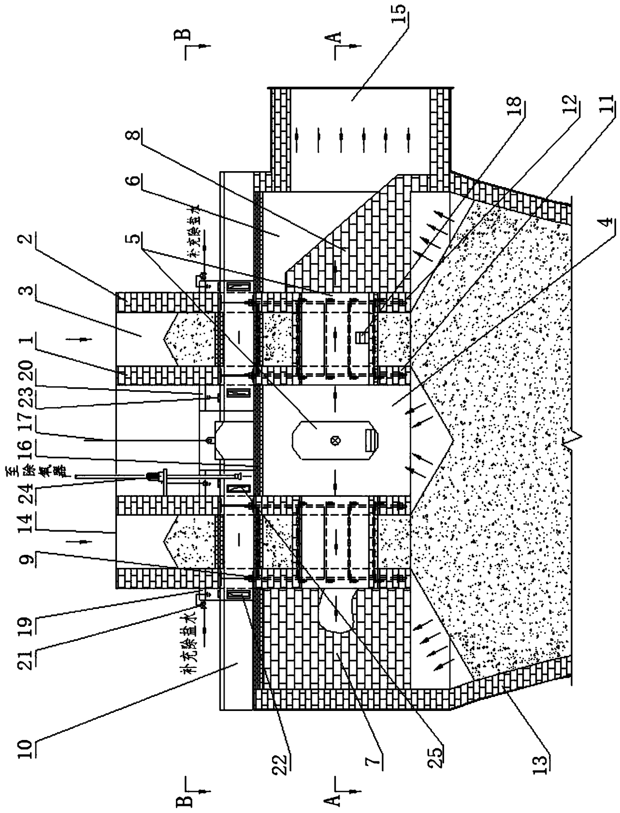
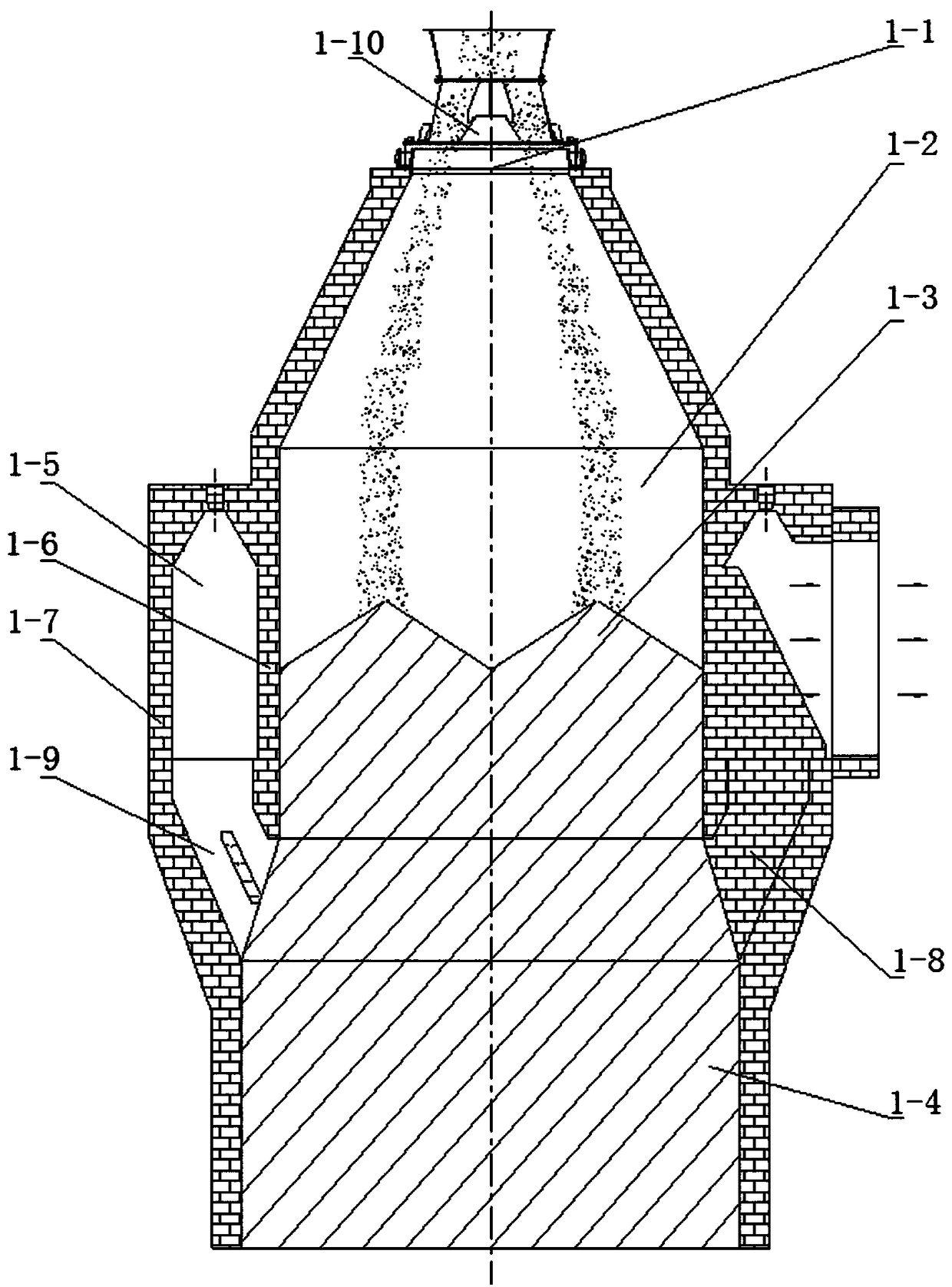
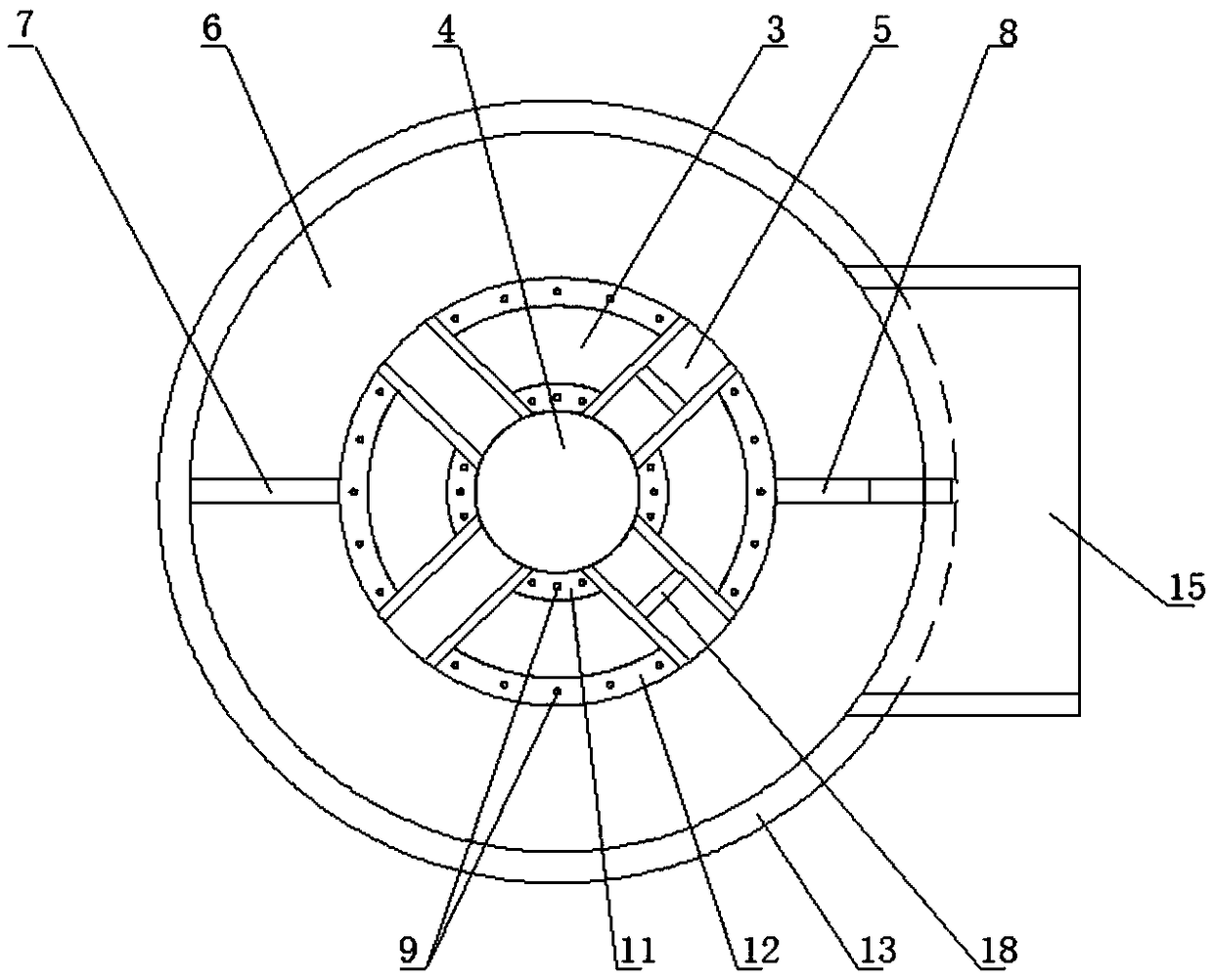
[0036] Such as Figure 2-Figure 4 As shown, the CDQ furnace with a water-cooled hanger and an annular pre-storage chamber according to the present invention includes a pre-storage chamber and a cooling chamber connected up and down; An annular pre-storage room composed of ring wall 11 and lower outer ring wall 12; a roof 16 is arranged on the top of the cooling outer wall 13, a water-cooling hanger 10 is arranged above the roof 16, and the upper inner ring wall 1 and the upper outer ring wall 2 are built on Above the water-cooled hanger 10; under the water-cooled hanger 10, a lower inner ring wall 11 and a lower outer ring wall 12 are set, and the ring passage formed by the lower inner ring wall 11 and the lower outer ring wall 12 is connected with the upper inner ring wall 1 and the upper outer ring The annular channel formed by the wall 2 is al...


PUM


Abstract

The invention relates to a dry quenching furnace with a water-cooling lifting frame and a ring-shaped pre-storage chamber and a working method of the quenching furnace. The pre-storage chamber of thedry quenching furnace is a ring-shaped pre-storage chamber commonly formed by an upper inner ring wall, an upper outer ring wall, a lower inner ring wall and a lower outer ring wall; a partitioning wall is arranged at one side of a ring-shaped air duct and a circulating gas outlet is formed in the other side of the ring-shaped air duct; a plurality of horizontal pre-storage gas flow channels penetrate through the lower inner ring wall and the lower outer ring wall to communicate a central drum with the ring-shaped air duct; the water-cooling lifting frame consists of a plurality of hollow beams, the outer ends of the hollow beams are communicated with an outer-ring water groove by desalted water inlets, and the other ends of the hollow beams are communicated with an inner-ring water grooveby desalted-water outlets; a floating ball valve is arranged in the outer-ring water groove, a long-axis submerged pump is arranged in the inner-ring water groove, and a water outlet of the long-axissubmerged pump is connected with an outer deaerator by a pipeline. The dry quenching furnace and the working method have the beneficial effects that the defects of the structure of the conventional dry quenching furnace can be overcome, segregation of cloths can be reduced, high pressure of the top part of the pre-storage chamber due to materials with large resistance in a unit material layer canbe reduced and the resistance loss of circulating gas can be reduced.

Description

technical field [0001] The invention relates to the technical field of dry quenching furnaces, in particular to a dry quenching furnace with a water-cooled hanger and an annular pre-storage chamber and a working method thereof. Background technique [0002] The CDQ furnace is an important energy-saving and environmental protection facility for coking production. It can cool the hot coke pushed out of the coke oven while recovering a large amount of heat energy carried by the coke, and also avoids the water and gas caused by wet coke quenching to the environment. Pollution, so it has been widely used in the field of coking. Coke oven production is cyclical and intermittent, and the coke oven system needs daily regular maintenance (the maximum daily maintenance time of the coke oven machine is 2 hours), so the time and frequency of coke loading into the CDQ furnace for cooling are affected by the coke oven production. On the other hand, the supply of coke in the cooling chamb...

Claims


Application Information

Patent Timeline
IPC IPC(8): C10B39/02
CPCC10B39/02
Inventor 白银石魏振东李旭东王满
Owner ACRE COKING & REFRACTORY ENG CONSULTING CORP DALIAN MCC
Why Eureka
Try Eureka