Rear-end gear chamber structure of diesel engine

A technology for gear chambers and diesel engines, applied in mechanical equipment, engine components, machines/engines, etc., can solve the problems of difficult manufacturing, difficult to assemble, inconvenient to maintain and adjust, etc., and achieves low manufacturing difficulty, easy assembly, and reduced manufacturing difficulty. effect on cost

Pending Publication Date: 2018-12-07
DONGFENG COMML VEHICLE CO LTD
View PDF14 Cites 3 Cited by
  • Summary
  • Abstract
  • Description
  • Claims
  • Application Information

AI Technical Summary

Problems solved by technology

[0010] The purpose of the present invention is to overcome the defects and problems of the prior art that are difficult to manufacture, difficult to assemble, and inconvenient to maintain and adjust the gear system, and to provide a gear system that is less difficult to manufacture, easy to assemble, and convenient to maintain and adjust the gear system. Diesel engine rear gear chamber structure

Method used


Image

  • Rear-end gear chamber structure of diesel engine
  • Rear-end gear chamber structure of diesel engine
  • Rear-end gear chamber structure of diesel engine

Examples


Embodiment 1

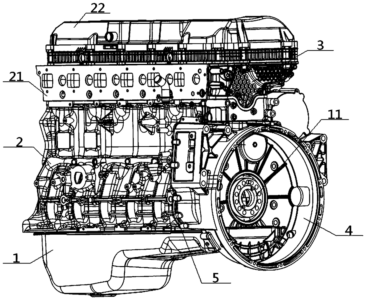
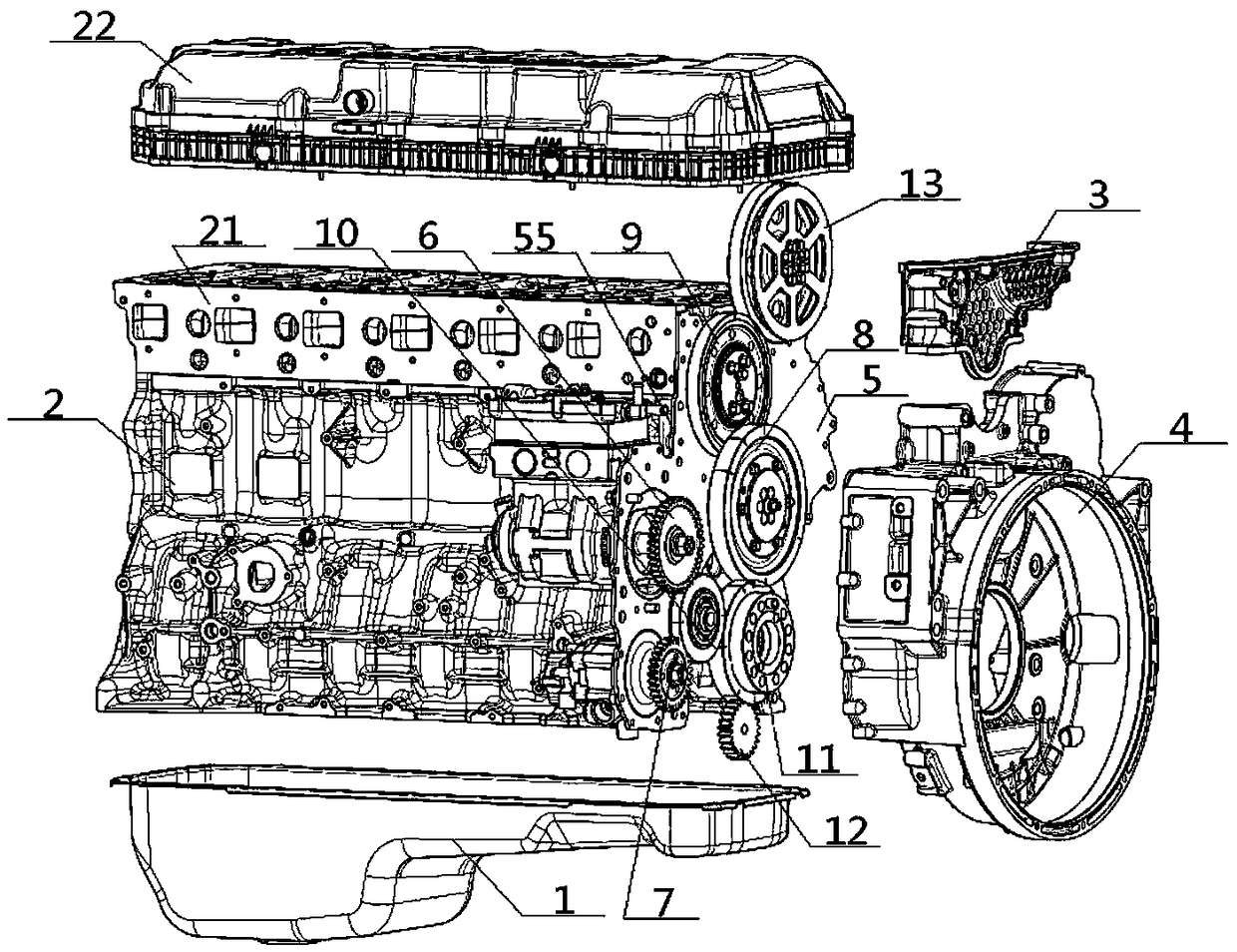
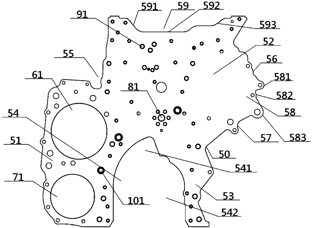
[0063] see Figure 1 to Figure 13 , a rear end gear chamber structure of a diesel engine, comprising a cylinder block 2, a cylinder head 21 and a timing gear chamber cover 3, a cylinder head 21 is arranged above the cylinder block 2, and the sides of the cylinder head 21 and the timing gear chamber cover The 3 sides of the diesel engine are connected; the rear gear chamber structure of the diesel engine also includes a rear end plate body 5 and a flywheel housing 4; the rear end plate body 5 includes a left plate body 51, an upper plate body 52 and a lower plate body 53, and the left The position near the top edge of the left plate body 51 on the right side of the plate body 51 is connected with the position near the bottom edge of the upper plate body 52 on the left side edge of the upper plate body 52, and the bottom edge of the upper plate body 52 is away from the left plate The position of the body 51 is connected with the top of the lower plate body 53, and the left side ...

Embodiment 2

[0065] Basic content is the same as embodiment 1, the difference is:

[0066]The middle part of the left plate body 51 is provided with an air compressor hole 61 and an oil pump hole 71 for corresponding installation with the air compressor gear 6 and the oil pump gear 7. The left plate body 51 is located between the air compressor hole 61 and the oil pump hole 71. There is No. 3 installation hole 101 on the position between them to install No. 3 falling gear 10; the position near the top of the bottom opening 54 on the upper plate body 52 is provided with No. 1 mounting hole 81 to install No. 1 falling gear 8, and the upper plate body The position between its top edge and the No. 1 mounting hole 81 on the 52 is provided with a No. 2 mounting hole 91 to install the No. 2 falling gear 9 . On the left plate body 51, there are empty upper left holes 611 and empty upper right holes 612 arranged side by side on the position between the top edge of the left plate body 51 and the top...

Embodiment 3

[0068] Basic content is the same as embodiment 1, the difference is:

[0069] The middle part of the flywheel housing 4 is provided with a concave flywheel chamber 112, and the middle part of the flywheel chamber 112 is provided with a through crankshaft gear hole 111, and the back side of the flywheel housing 4 is provided with an oil bottom at the position directly below the crankshaft gear hole 111. The shell matching surface 14 is connected with the oil pan 1, and the top of the flywheel housing 4 is provided with a gear chamber cover fitting seat 31, the bottom surface of which is higher than the flywheel chamber 112, and the gear chamber cover fitting seat 31 The top surface is provided with a recessed gear chamber cover matching groove 32, and the gear chamber cover matching groove 32 is wedged with the lower extension end 33 of the cover embedded in it; the back of the flywheel housing 4 is located on the left side of the crankshaft gear hole 111 The parts on the side ...


PUM


Abstract

The invention relates to a rear-end gear chamber structure of a diesel engine. The rear-end gear chamber structure comprises a timing gear chamber cover, a rear-end plate body and a flywheel shell, wherein the middle of a left plate body in the rear-end plate body is connected with an air compressor gear, an oil pump gear and a third idle gear, the middle of an upper plate body is connected with afirst idle gear and a second idle gear, a camshaft gear is arranged on the upper plate body, a crankshaft gear and an oil pump gear are sequentially arranged in the bottom vacancy opening from top tobottom, and the front and back surfaces of the rear-end plate body are connected with a cylinder body/ a cylinder cover, the timing gear chamber cover/the flywheel shell respectively; the bottom surface of the cylinder body is connected with an oil pan, the top surface of the cylinder body is connected with the bottom surface of a housing of the cylinder cover through the cylinder cover, the right end of the housing of cylinder cover is connected with the top of the timing gear chamber cover, the bottom of the timing gear chamber cover is in wedge connection with a gear chamber cover matchinggroove formed in the top of the flywheel shell through a cover downward extending end. The rear-end gear chamber structure has the advantages of being convenient in manufacturing, assembling, maintenance and adjustment of gear system, light in weight, high in overall rigidity, and good in noise reduction effect.

Description

technical field [0001] The invention relates to a gear chamber structure of a diesel engine, which belongs to the field of engines and related systems, in particular to a rear-end gear chamber structure of a diesel engine, which is particularly suitable for reducing manufacturing difficulty and facilitating assembly, maintenance and adjustment of gear systems. Background technique [0002] At present, because the operation fluctuation of the flywheel end of the crankshaft of the diesel engine is more stable than that of the front end, more and more diesel engines place the gear chamber at the rear for the sake of vibration reduction and noise reduction, that is, the gear chamber is arranged at the rear end of the engine block. The flywheel end of the crankshaft outputs the power required by the gear system. In the prior art, the rear gear chamber is usually integrally cast directly from the cylinder body, or the gear chamber is assembled to the rear end of the cylinder body ...

Claims


Application Information

Patent Timeline
Patent Type & Authority Applications(China)
IPC IPC(8): F02F7/00
CPCF02F7/0021F02F7/0073
Inventor 邓学勤李智王东国玉莹张晓银覃欢欢
Owner DONGFENG COMML VEHICLE CO LTD
Why Eureka
Try Eureka