Lubricating oil filling machine

An oil injection machine and lubricating oil technology, which is applied in the direction of lubricating oil control valves, lubricating parts, engine lubrication, etc., can solve the problems of inconvenient oil injection, shorten the service life of equipment, and insufficient oil injection, so as to improve oil injection efficiency and reduce The effect of small workload and easy replacement

Inactive Publication Date: 2018-12-07
丰县王领农机服务专业合作社
View PDF0 Cites 3 Cited by
  • Summary
  • Abstract
  • Description
  • Claims
  • Application Information

AI Technical Summary

Problems solved by technology

[0002] At present, the lubrication of the hinged parts of vehicles and construction machinery is mostly manual oiling or hand-held oiling one by one, which is usually called buttering, but for some large-scale mechanical equipment, oiling is very inconvenient, and there are many points that need to be oiled , so that the driver cannot fill the equipment with oil in time or the amount of oil is not enough, which will lead to abnormal wear of the equipment and greatly reduce the service life of the equipment

Method used


Image

  • Lubricating oil filling machine
  • Lubricating oil filling machine
  • Lubricating oil filling machine

Examples


Embodiment approach 1

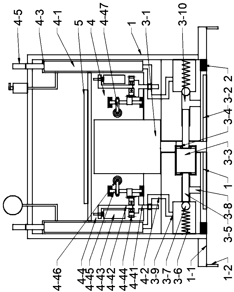
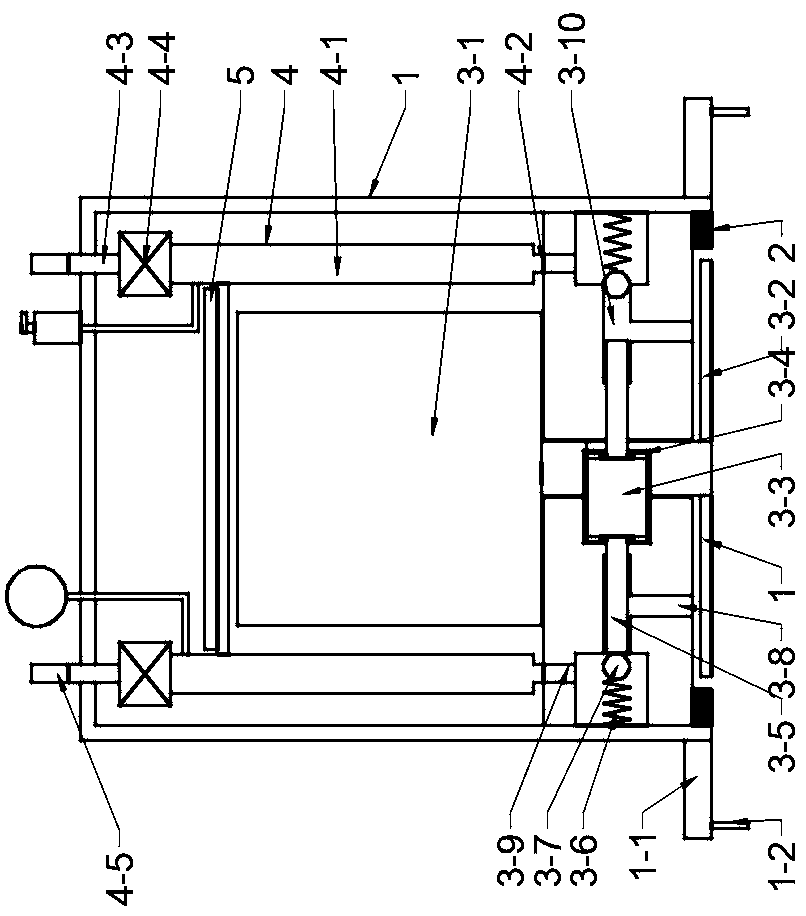
[0023] Such as figure 1 As shown, a lubricating oil injection machine includes a housing 1, a rubber oil pressure plate 2, an anti-tilt dustproof system, an oil pump device 3, an oil separator 4 and a control system 5; the oil pump device 3 is installed in the housing 1 The bottom of the housing 1 is installed with a rubber pressure oil plate 2, and the oil separator 4 and the control system 5 are installed in the housing 1; the oil pump device 3 includes a motor 3-1, a spiral oil scraper 3-2, and an eccentric wheel 3-3 , collar 3-4, plunger 3-5, spring 3-6, steel ball 3-7, oil inlet 3-8, oil outlet 3-9 and oil channel 3-10; the spiral oil scraper 3-2 is located at the bottom of the housing 1 and is fixedly connected with the output shaft of the motor 3-1; the oil inlet 3-8 is evenly distributed on the bottom surface of the housing 1 in the circumferential direction, and the oil inlet 3-8 is located on the spiral oil scraper 3- 2 within the radius of rotation; the oil outlet ...

Embodiment approach 2

[0037] Such as image 3 As shown, the electromagnetic valve 4 directly adopts an electromagnetic valve.

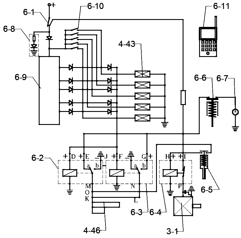
[0038] Such as Figure 4 As shown, the control system 5 includes a power switch 5-1, a solenoid valve switch 5-2, an oil pump relay 5-3, a pressure controller 5-4, a remote control chip 5-5, a position sensor 5-6, and an alarm 5-7, power indicator light 5-8 and remote controller 5-9; the main circuit of the control system 5 is connected to the power supply, and is provided with a power switch 5-1; the main circuit connects four branch circuits, all the way connected to the power indicator light 5 -8; the other road is connected to the remote controller chip 5-5, and the remote controller chip 5-5 and the remote controller 5-9 realize wireless signal transmission; the third route is a plurality of solenoid valve switches 5-2 and corresponding solenoid valve valves 4- 4 in series and then in parallel, then in series with the pressure controller 5-4, the pressure controller...

Embodiment approach 3

[0044] Such as Figure 5 As shown, the electric push rod 4-46 in Embodiment 1 is replaced by a motor 4-48, the front end of the output shaft of the motor 4-48 is equipped with a power output gear 4-49, and the upper part of the disc shift fork 4-45 is equipped with a transmission Gear 4-50, output gear 4-49 meshes with transmission gear.


PUM


Abstract

The invention relates to a lubricating oil filling machine. An oil pump device is mounted at the bottom of a shell. The bottom of the shell is provided with a rubber oil pressing pan. Oil distributorsand a control system are mounted in the shell. A spiral oil scraping plate of the oil pump device is fixedly connected with an output shaft of a motor. Oil inlets are located within the rotating radius of the spiral oil scraping plate. Oil outlets communicate with the oil inlets through pipes to form an oil channel. Springs and steel balls are arranged in the oil channel. A plunger is arranged inthe oil channel. The outer end of the plunger is provided with an eccentric wheel. The eccentric wheel is in gearing-down connection with the output shaft of the motor. The plunger does reciprocatingmotion in the oil channel under the action of the eccentric wheel and a clamp ring to push the steel balls to squeeze out grease. Oil storage cavities of the oil distributors are connected with the corresponding oil inlets and the corresponding oil outlets. The oil inlets are arranged corresponding to the oil outlets of the oil pump device. The oil outlets are connected with oil filling hoses tofill oil to oil filling points one by one. The lubricating oil filling machine can control the oil filling volume, improve the oil filling efficiency and avoid waste and is operated through a remote controller, is safe and sanitary and facilitates replacing of an oil drum.

Description

technical field [0001] The invention relates to an oil injection machine, in particular to a lubricating oil injection machine. Background technique [0002] At present, the lubrication of the hinged parts of vehicles and construction machinery is mostly manual oiling or hand-held oiling one by one, which is usually called buttering, but for some large-scale mechanical equipment, oiling is very inconvenient, and there are many points that need to be oiled , so that the driver cannot fill the equipment with oil in time or does not fill enough oil, resulting in abnormal wear and tear of the equipment and greatly reducing the service life of the equipment. Contents of the invention [0003] In order to solve the above technical problems, the present invention provides a lubricating oil injection machine, which can regularly and quantitatively inject oil to multiple oil injection points according to the pre-programmed program, get rid of dirty, tired and dangerous, and complet...

Claims


Application Information

Patent Timeline
Patent Type & Authority Applications(China)
IPC IPC(8): F16N7/38F16N23/00F16N25/04F16N29/02F16N29/04
CPCF16N7/38F16N23/00F16N25/04F16N29/02F16N29/04F16N2210/04F16N2260/04F16N2270/60
Inventor 李兴合
Owner 丰县王领农机服务专业合作社
Why Eureka
Try Eureka