A Bandgap Reference Source with High Power Supply Rejection Ratio

A technology with high power supply rejection ratio and reference source, which is applied in the direction of adjusting electrical variables, control/regulation systems, instruments, etc., can solve problems such as circuit complexity and power consumption increase, and achieve improved power supply rejection ratio, simple circuit structure, Effect of High Power Supply Rejection PSR Capability

Active Publication Date: 2019-11-01
UNIV OF ELECTRONICS SCI & TECH OF CHINA
View PDF6 Cites 0 Cited by
  • Summary
  • Abstract
  • Description
  • Claims
  • Application Information

AI Technical Summary

Problems solved by technology

[0007] The purpose of the present invention is to propose a bandgap reference source with a high power supply rejection ratio for the above-mentioned traditional bandgap reference circuit that needs to add additional circuits to improve the power supply voltage rejection ratio, resulting in circuit complexity and increased power consumption. , improve the power supply rejection ratio in the internal circuit of the bandgap reference source, and at the same time the bandgap reference source proposed by the present invention may not use an op amp structure, which avoids the problem of limiting the accuracy of the bandgap reference source due to the introduction of op amp input offset

Method used


Image

  • A Bandgap Reference Source with High Power Supply Rejection Ratio
  • A Bandgap Reference Source with High Power Supply Rejection Ratio
  • A Bandgap Reference Source with High Power Supply Rejection Ratio

Examples


Embodiment Construction

[0044] The present invention will be described in detail below in conjunction with the accompanying drawings and specific embodiments.

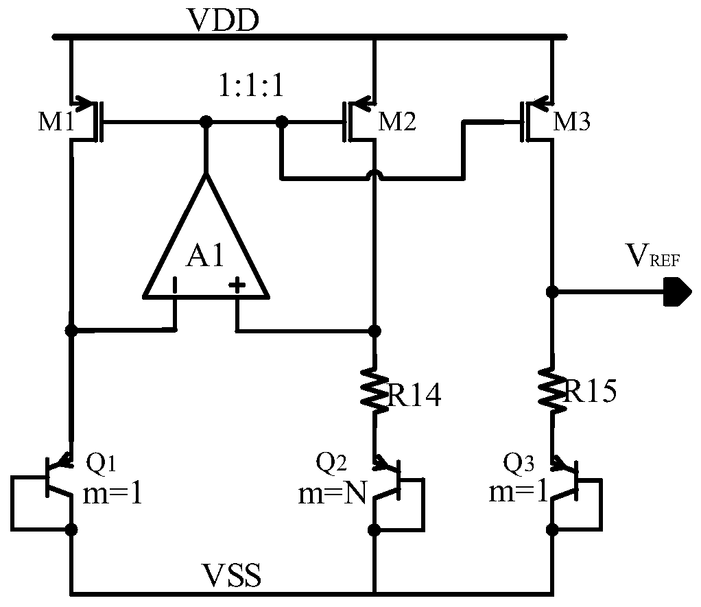
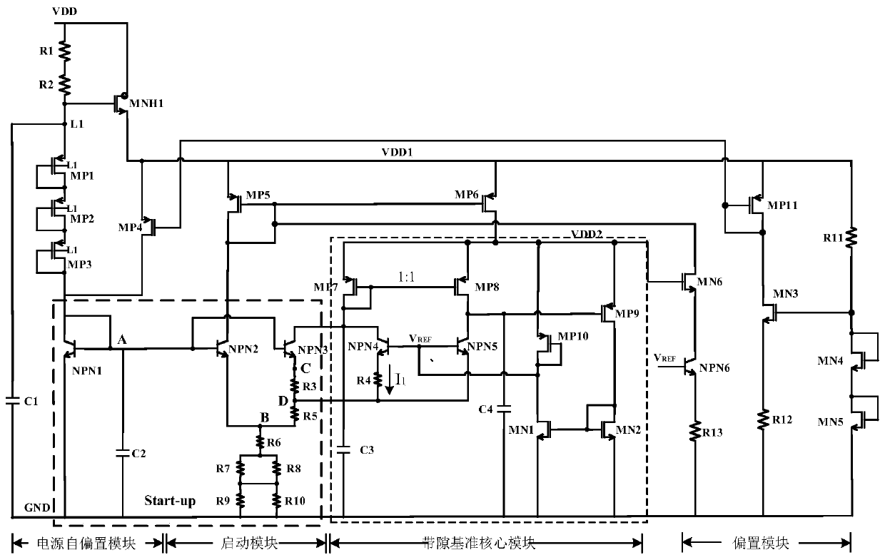
[0045] A bandgap reference source with a high power supply rejection ratio proposed by the present invention includes a power supply self-bias module, a start-up module, a bandgap reference core module and a bias module, wherein the structure of the power supply self-bias module is as follows figure 2 As shown, the power supply self-bias module includes a first resistor R1, a second resistor R2, a first PMOS transistor MP1, a second PMOS transistor MP2, a third PMOS transistor MP3, a first capacitor C1, a second capacitor C2, and a seventh NMOS transistor. tube MNH1 and the first switch tube, the power supply voltage VDD passes through the series structure of the first resistor R1 and the second resistor R2 to generate the gate bias signal of the seventh NMOS transistor MNH1, which is connected to the gate of the seventh NMOS transistor MNH1 ...


PUM


Abstract

A bandgap reference source with high power supply rejection ratio belongs to the technical field of electronic circuits. It includes a power supply self-bias module, a start-up module, a bandgap reference core module and a bias module. The power supply self-bias circuit converts the power supply voltage into the first power rail signal through the seventh NMOS transistor as the power rail of the bias module, and the start-up module Together with the power supply self-bias module, it establishes the bias for the bias module, and the bias module provides bias for the bandgap reference core module; the second switch tube and the third switch tube of the start-up circuit work when the power supply is established to prevent the entire circuit from staying In the zero state, exit after the circuit enters the normal working state; the resistor network in the startup circuit is used to adjust the negative temperature coefficient voltage of the bandgap reference core module, and the adjusted negative temperature coefficient voltage and the positive temperature generated by the bandgap reference core module The coefficient voltages are superimposed to generate a reference voltage. The invention has the characteristics of higher power supply suppression ability, simple structure, high precision and high stability.

Description

technical field [0001] The invention belongs to the technical field of electronic circuits, and in particular relates to the design of a bandgap reference circuit with high power supply rejection ratio. Background technique [0002] In the design fields of high-performance analog integrated circuits, digital-analog hybrids, digital and power management systems, reference voltage sources are very important and commonly used modules, and are often used in circuits such as analog and digital converters, power converters, and power amplifiers. Performance directly affects the accuracy and stability of the entire system. Since the output of the bandgap reference circuit is connected to the error amplifier or operational amplifier and becomes part of the differential input of the error amplifier, if the power supply ripple or noise cannot be well suppressed in the bandgap reference circuit, then the ripple Voltage and power supply noise will become part of the input signal to the...

Claims


Application Information

Patent Timeline
Patent Type & Authority Patents(China)
IPC IPC(8): G05F1/575
CPCG05F1/575
Inventor 明鑫胡黎冯旭东潘溯张春奇王卓张波
Owner UNIV OF ELECTRONICS SCI & TECH OF CHINA
Why Eureka
Try Eureka