
Sliding mode control-based MMC (Modular Multi-Level Converter) circulating current suppression method

A circulating current suppression, sliding mode technology, applied in power transmission AC network, output power conversion device, AC power input conversion to DC power output, etc. and other problems, to achieve the effects of good dynamic characteristics, reduced distortion rate, and fast response speed

Inactive Publication Date: 2018-12-07
NORTH CHINA ELECTRIC POWER UNIV (BAODING)
View PDF0 Cites 4 Cited by
  • Summary
  • Abstract
  • Description
  • Claims
  • Application Information

AI Technical Summary

Problems solved by technology

The circulating current is superimposed on the current of the upper and lower bridge arms. If no special auxiliary control strategy is adopted, on the one hand, the rated current capacity of the power switching device will be increased, which will increase the system cost; on the other hand, the loss will be increased, and the power switch tube will heat up seriously , or even burned, affecting the service life of the device

Method used


Image

  • Sliding mode control-based MMC (Modular Multi-Level Converter) circulating current suppression method
  • Sliding mode control-based MMC (Modular Multi-Level Converter) circulating current suppression method
  • Sliding mode control-based MMC (Modular Multi-Level Converter) circulating current suppression method

Examples


Embodiment Construction

[0019] The MMC circulation suppression method based on the sliding mode controller will be described in detail below with reference to the accompanying drawings and examples.

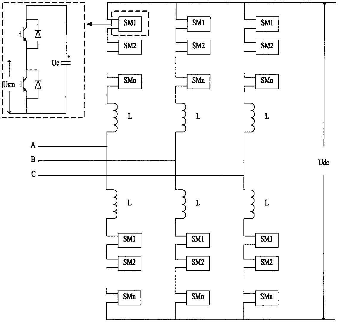
[0020] Depend on figure 1 It can be seen that in the MMC topology diagram, the modular multilevel (MMC) has 6 bridge arms, and each bridge arm is formed by cascading many sub-modules. This example uses a 21-level MMC high-voltage direct current transmission system, so each bridge arm has 20 sub-modules, 10 for each of the upper and lower bridge arms. Taking the A-phase bridge arm as an example, build a model in the electromagnetic transient simulation software PSCAD / EMTDC, the AC system voltage is 230kV, and the rated power is 1200MVA. The specific suppression measures are as follows:

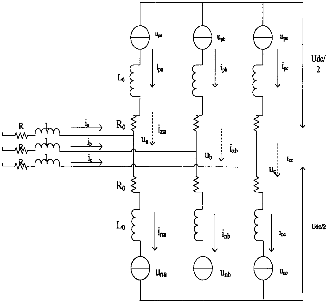
[0021] First, by monitoring the current i of the upper and lower bridge arms of the MMC pj and i qj , using the bridge arm current formula

[0022]

[0023] The size of the bridge arm circulation can be calculated...


PUM


Abstract

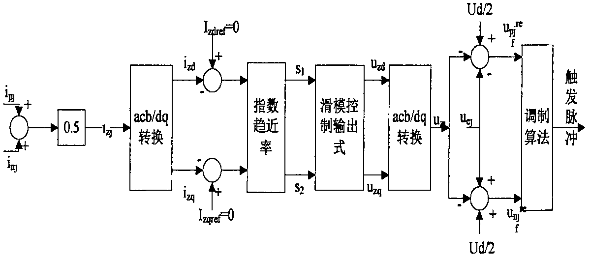
The invention relates to a sliding mode control-based MMC (Modular Multi-Level Converter) circulating current suppression method. With the method adopted, the quick suppression of the internal circulating current of a modular multi-level converter (MMC) device can be realized. According to the method, feedback linearization is carried out to decouple a system, and a variable-structure controller is designed to perform circulating current suppression. The method comprises the following main steps that: the current of upper arms and lower arms is measured, and internal circulating current is calculated; Park transformation is performed on the circulating current; the difference of a measured value and a reference value is calculated, and the difference is substituted into exponential reaching law calculation, an intermediate variable is calculated and is transmitted to a sliding mode controller, and the quadrature-axis component and direct-axis component of a circulating current calculation voltage value are obtained by means of the calculation of the controller; and the components of the circulating current calculation voltage value are substituted into a circulating current calculation formula, so that the reference voltage values of the upper arms and lower arms can be obtained; and the reference voltage values are transmitted to a modulation module, and trigger signals of modulated waves are generated, so that the on-off of sub-modules in the MMC can be controlled. When the sliding mode controller designed in the method performs circulating current suppression, the sliding mode controller has higher response speed and has higher stability after suppressing frequency-doubled circulating current.

Description

technical field [0001] The patent of the invention relates to the field of power electronics technology in high-voltage transmission systems, and is mainly applied to the modular multi-level link in flexible direct current transmission, and specifically relates to a control measure for suppressing circular current between modules. Background technique [0002] With the rapid development of clean energy power generation technologies represented by wind power and solar power, the voltage source converter-high voltage direct current (VSC-HVDC) system based on voltage source converters has become a research hotspot in power system technology. The traditional two-level converter or three-level converter using the technology of direct series connection of power switching devices is an effective way to improve the application voltage level and system capacity of the voltage source converter. However, this type of topology has a large output voltage harmonic content, often requires ...

Claims


Application Information

Patent Timeline
IPC IPC(8): H02J3/36H02M7/483H02M1/32
CPCH02J3/36H02M1/32H02M7/483Y02E60/60
Inventor 刘青焦晓鹏
Owner NORTH CHINA ELECTRIC POWER UNIV (BAODING)
Learn More