High-speed electric spindle structure with intelligent monitoring and quick maintenance functions
A high-speed electric spindle and intelligent monitoring technology, which is applied in the testing of machines/structural components, mechanical bearings, mechanical components, etc., can solve the problems of complex assembly and disassembly, heavy workload, and long time for spindle maintenance, and achieve good results. Anti-electromagnetic interference performance, realizing intelligence, and reducing losses
- Summary
- Abstract
- Description
- Claims
- Application Information
AI Technical Summary
Problems solved by technology
Method used
Image
Examples
Embodiment 1
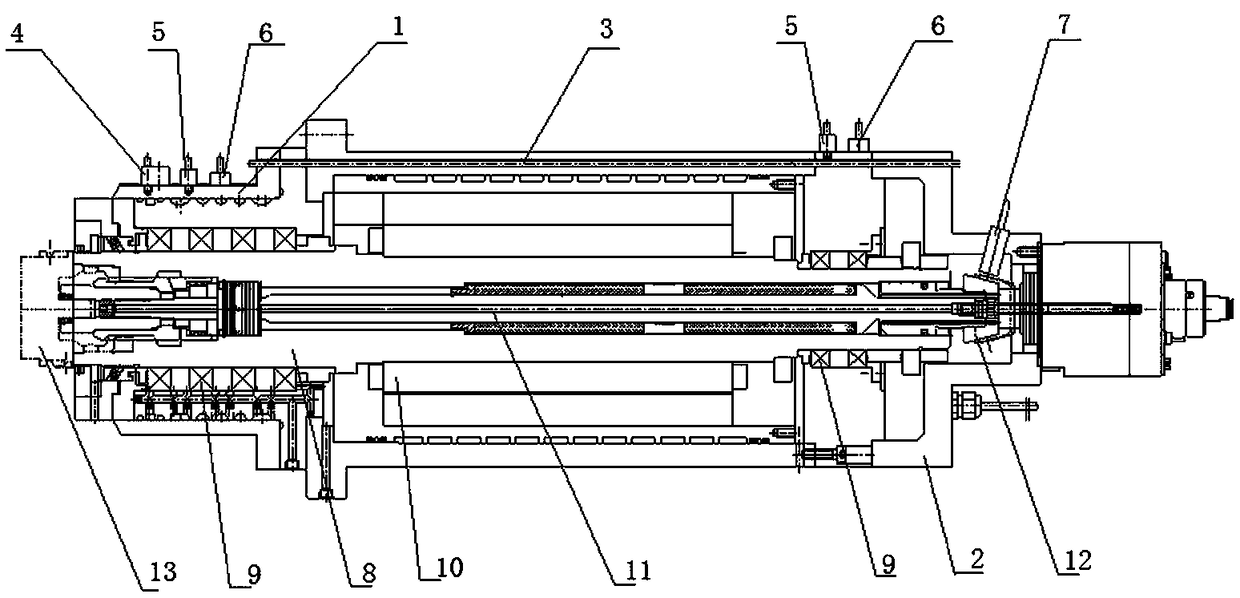
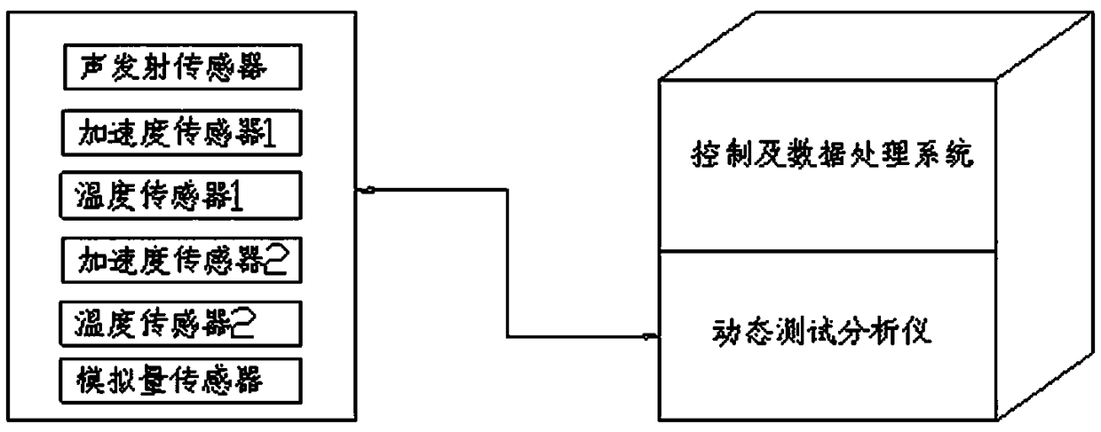
[0034] As the most basic implementation of the present invention, a high-speed electric spindle structure with intelligent monitoring and quick maintenance is disclosed, such as figure 1 with 2 , Including an outer shell and a spindle body set in the shell; the shell includes a front bearing seat 1, a rear bearing seat 2 and a middle shell sleeve 3, and the shell is provided with sound waves for monitoring the spindle body Sensor 4, acceleration sensor 5, temperature sensor 6, cone detection ring 12 and analog sensor 7;
[0035] The main shaft body includes a precision taper sleeve 14 and a main shaft rod 8. The front and rear ends of the main shaft rod 8 are both sleeved with transition bearings 9 and the middle shell sleeve 3 of the housing is provided with a rotating shaft for driving the main shaft rod 8. The driving device 10; the spindle rod 8 is inserted in the middle of the housing through the transition bearings 9 at both ends, and the transition bearings 9 at both ends c...
Embodiment 2
[0038] As a preferred embodiment of the present invention, a high-speed electric spindle structure with intelligent monitoring and quick maintenance is disclosed, such as figure 1 , 2 And 3, including an outer shell and a main shaft body set in the shell; the shell includes a front bearing seat 1, a rear bearing seat 2 and a middle shell sleeve 3, and the shell is provided with a monitor for the main shaft body Acoustic wave sensor 4, acceleration sensor 5, temperature sensor 6, cone detection ring 12 and analog sensor 7;
[0039] The main shaft body includes a precision taper sleeve 14 and a main shaft rod 8. The front and rear ends of the main shaft rod 8 are both sleeved with transition bearings 9 and the middle shell sleeve 3 of the housing is provided with a rotating shaft for driving the main shaft rod 8. The driving device 10; the spindle rod 8 is inserted in the middle of the housing through the transition bearings 9 at both ends, and the transition bearings 9 at both ends...
Embodiment 3
[0044] This embodiment provides a new type of high-speed electric spindle structure applied to the intelligent monitoring and quick assembly and disassembly adjustment of CNC machine tools. Such as figure 2 , The main shaft body parts are split into precision taper sleeve 14 and spindle rod 8 two precisely connected and installed parts. When the taper hole of the precision taper sleeve 14 part is damaged, only the precision taper sleeve 14 part needs to be removed for replacement and installation , The operation is simple; after the main shaft body is damaged, only the 14 parts of the front precision taper sleeve are replaced, the cost is greatly reduced, and the operating system itself has been verified for a long time. After the taper sleeve is replaced, the original high-speed and operating accuracy performance can be maintained.
[0045] This technical solution integrates intelligent monitoring, discrimination and control with advanced high-speed motorized spindle technology,...
PUM
 Abstract
Description
Claims
Application Information
 - R&D
- Intellectual Property
- Life Sciences
- Materials
- Tech Scout
- Unparalleled Data Quality
- Higher Quality Content
- 60% Fewer Hallucinations
Browse by: Latest US Patents, China's latest patents, Technical Efficacy Thesaurus, Application Domain, Technology Topic, Popular Technical Reports.
© 2025 PatSnap. All rights reserved.Legal|Privacy policy|Modern Slavery Act Transparency Statement|Sitemap|About US| Contact US: help@patsnap.com


