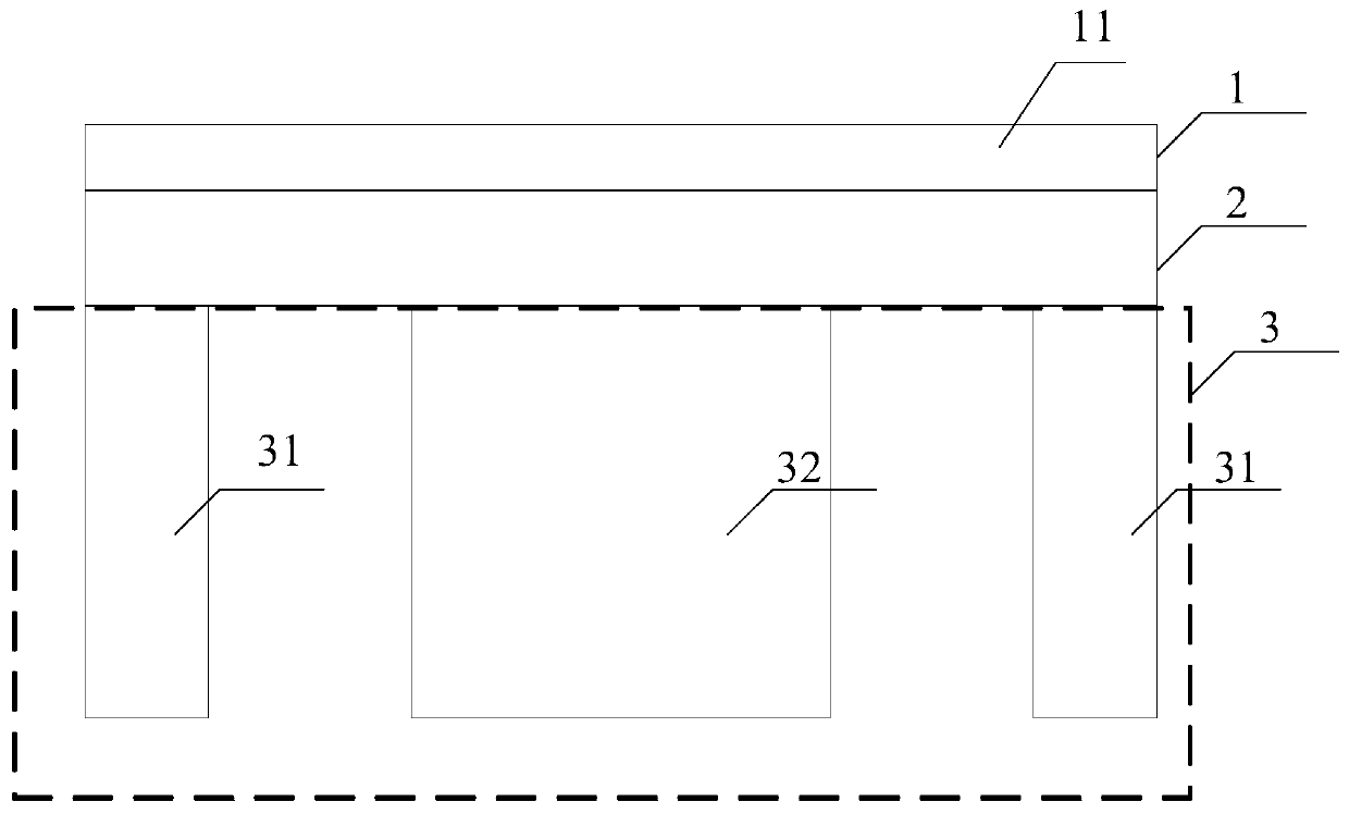
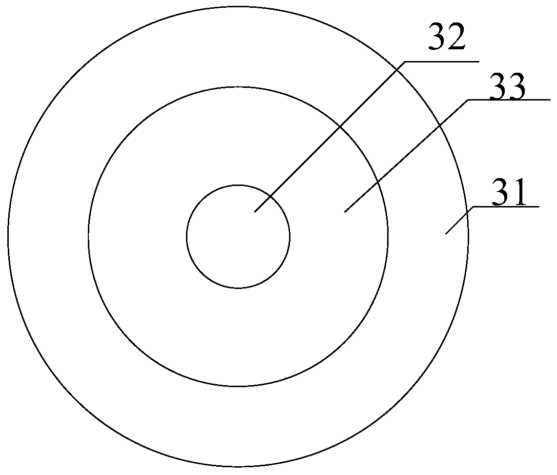
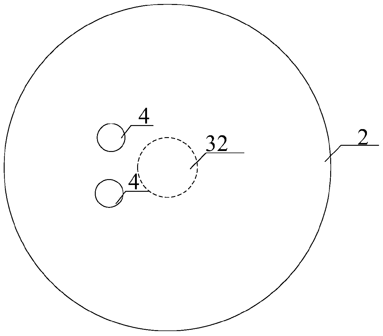
A magnetron sputtering coating cathode structure
A technology of magnetron sputtering coating and cathode structure, which is applied in sputtering coating, vacuum evaporation coating, ion implantation coating and other directions, can solve the problems of magnetic field attenuation, etc. stable effect
- Summary
- Abstract
- Description
- Claims
- Application Information
AI Technical Summary
Problems solved by technology
Method used
Image
Examples
Embodiment 1
[0086] Specifically, the back plate 2 has a diameter of 91.6 mm and a thickness of 6.5 mm, and the first iron core of the first magnetic field generating structure 31 is a ring structure with an inner diameter of 71.6 mm, an outer diameter of 91.6 mm, and a height of 25mm, the diameter of the wire in the first excitation coil is 1mm, and the conductivity is 6×10 7 S / m, the number of turns is 3500 turns. The second iron core in the second magnetic field generating structure 32 is a cylindrical structure with a height of 25mm and a diameter of 27mm. The diameter of the wire in the second excitation coil is 1mm and the conductivity is 6. ×107S / m, the number of turns is 3500 turns, the plane figure of the target structure 1 is a circle with a diameter of 91.6mm.
[0087] Perform geometric modeling of the above-mentioned cathode structure, define the physical properties of air, set the first target material 11 as a titanium target material, and set the thickness of the first target mat...
Embodiment 2
[0090] In the embodiment of the present invention, the target structure 1 only includes the first target 11, the top view of the target structure 1 and the back plate 2 is circular, and the back plate 2 is The copper back plate, specifically, the diameter of the back plate 2 is 91.6 mm, the thickness is 6.5 mm, the inner diameter of the first iron core in the first magnetic field generating structure 31 is 71.6 mm, the outer diameter is 91.6 mm, and the height is 25mm, the diameter of the wire in the first excitation coil is 1mm, and the conductivity is 6×10 7 S / m, the number of turns is 3500 turns, the height of the second core in the second magnetic field generating structure 32 is 25mm, the diameter is 27mm, the diameter of the wire in the second excitation coil is 1mm, and the conductivity is 6×10 7 S / m, the number of turns is 3500 turns, and the plane figure of the target structure 1 is a circle with a diameter of 91.6 mm.
[0091] Specifically, the COMSOL Multiphysics softwa...
Embodiment 3
[0097] In the embodiment of the present invention, the target structure 1 includes two targets: a first target 11 and a second target 12. That is, the target structure 1 is a splicing target structure, and the target structure 1 and the The shape 2 of the backing plate is circular, and the backing plate 2 is a copper backing plate. Specifically, the shape of the second target material 12 is a disc shape, and a number of symmetrical pastes are attached on part of the racetrack area 13 of the first target material 11 The second target material 12, the diameter of the back plate 2 is 91.6mm, the thickness is 6.5mm, the inner diameter of the first iron core in the first magnetic field generating structure 31 is 71.6mm, the outer diameter is 91.6mm, and the height is 25mm , The diameter of the wire in the first excitation coil is 1mm, and the conductivity is 6×10 7 S / m, the number of turns is 3500 turns, the height of the second core in the second magnetic field generating structure ...
PUM
| Property | Measurement | Unit |
|---|---|---|
| diameter | aaaaa | aaaaa |
| diameter | aaaaa | aaaaa |
| diameter | aaaaa | aaaaa |
Abstract
Description
Claims
Application Information
 - R&D
- Intellectual Property
- Life Sciences
- Materials
- Tech Scout
- Unparalleled Data Quality
- Higher Quality Content
- 60% Fewer Hallucinations
Browse by: Latest US Patents, China's latest patents, Technical Efficacy Thesaurus, Application Domain, Technology Topic, Popular Technical Reports.
© 2025 PatSnap. All rights reserved.Legal|Privacy policy|Modern Slavery Act Transparency Statement|Sitemap|About US| Contact US: help@patsnap.com


