
Miniature air-compression generator

A generator and air compressor technology, applied in engines, wind power generation, wind engines, etc., can solve the problems of not conforming to localization, difficulty in large-scale application, high price, etc., and achieve the effect of convenient space allocation on the bomb

Inactive Publication Date: 2018-12-11
杭州亨安科技有限公司
View PDF2 Cites 2 Cited by
  • Summary
  • Abstract
  • Description
  • Claims
  • Application Information

AI Technical Summary

Problems solved by technology

It is precisely because of these shortcomings of thermal batteries that disposable lithium batteries have also begun to be used in some ammunition in recent years. Its miniaturization, standardization, and stable output are superior to thermal batteries, but it also has a fatal weakness, and its storage life is difficult to reach 10 years. If it is stored for more than 10 years, a passivation film will be formed, and the voltage response will lag. At present, only the Israeli TADIRAN brand lithium battery can solve this problem well. The storage life is 20 years without lag, but the price is very high. It is difficult to realize large-scale application, and because it is an imported battery, it does not meet the requirements of localization
In addition, this kind of traditional power supply itself is charged, and there is a risk of short circuit causing fire during the assembly process, and there must be a special control circuit to control the output when in use.

Method used


Image

  • Miniature air-compression generator
  • Miniature air-compression generator
  • Miniature air-compression generator

Examples


Embodiment Construction

[0016] The present invention will be further described in detail below in conjunction with the accompanying drawings and examples. The following examples are explanations of the present invention and the present invention is not limited to the following examples.

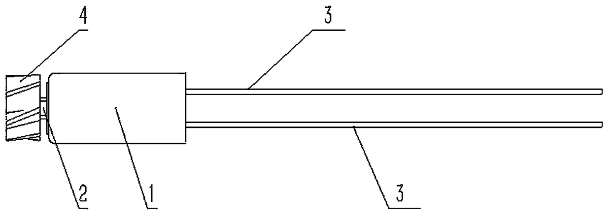
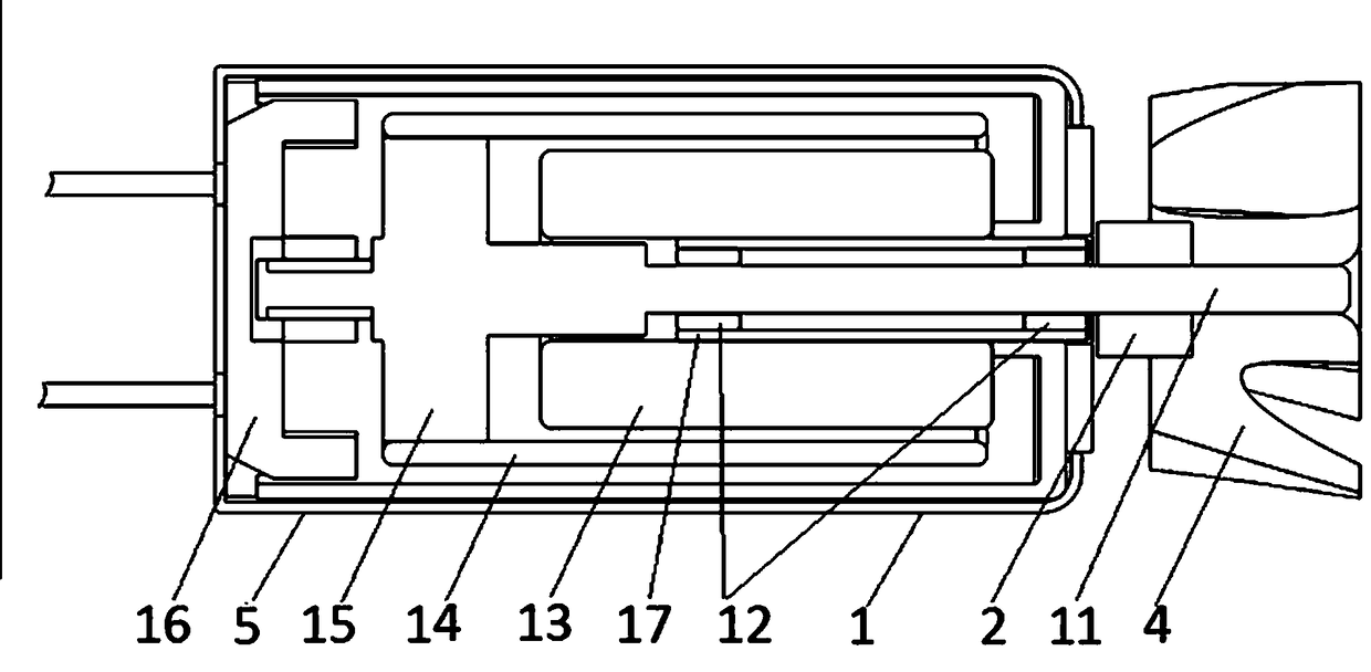
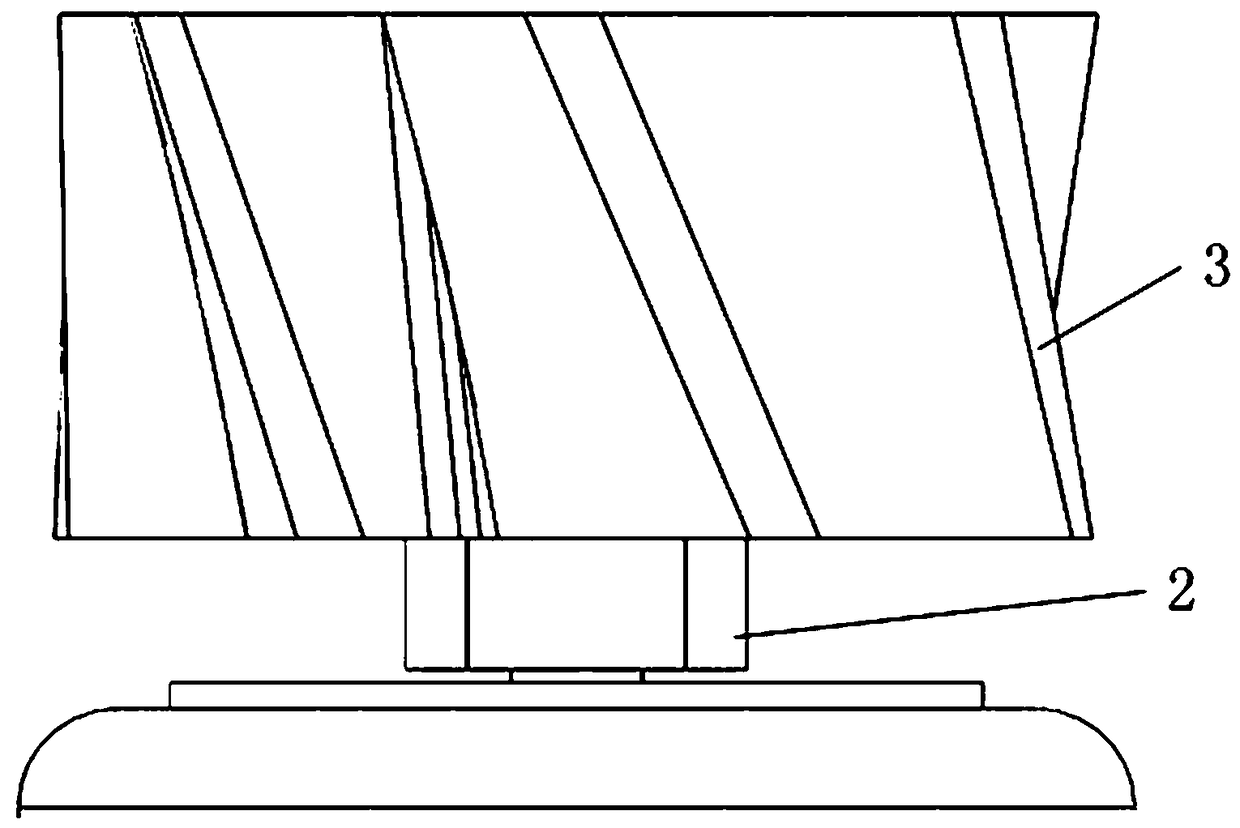
[0017] see Figure 1-6 , the miniature air compressor generator in the present embodiment is made up of motor body 1, axle sleeve 2, output line 3 and blade 4, and output line 3 is connected with motor body 1, and motor body 1 includes motor case 5, is installed in electric motor The motor shaft 11, support 15, coil 14, magnetic cover 13 and rear cover 16 in the casing 5, the blade 4 passes through one end of the motor shaft 11 and is installed on the shaft sleeve 2, the other end of the motor shaft 11 is connected with the support 15, and the coil 14 is installed on the bracket 15, the magnetic sleeve 13 is connected with the motor body 1 through the nested shaft 17, two bearing bushes 12 are embedded in the two en...


PUM


Abstract

The invention relates to a miniature air-compression generator, comprising a motor body, a shaft sleeve, output wires and a blade. The output wires are connected with the motor body. The motor body includes: a motor housing; a motor shaft, a support, a coil, a magnetic sleeve and a rear cover mounted in the motor housing. The blade is passed through one end of the motor shaft and fitted to the shaft sleeve; the other end of the motor shaft is connected with the support. The coil is mounted on the support. The magnetic sleeve is connected with the motor body via a socket shaft. Two bearing bushes are embedded in the two ends of the inside of the socket shaft. The motor shaft is mounted by being passed through the two bearing bushes. A gap is provided between the motor shaft and each bearingbush. The blade is used herein as a driving component; when the blade is driven by wind to rotate, the motor shaft drives the coil to rotate around the magnetic sleeve, current is output, and power generation is finished. The startup speed and rotation speed are changed by adjusting the blade specification so as to adapt to different flight environments and startup conditions; the requirement onminiaturization can be met. The whole miniature air-compression generator which is of slender cylinder structure is applicable to projectile structures and allows on-projectile space to be conveniently allocated.

Description

technical field [0001] The invention relates to the technical field of missile-borne power supplies, in particular to a micro-generator using air pressure to generate electricity. Background technique [0002] The micro air compressor generator is a new missile-borne power supply solution that uses the wind resistance to drive the blades to generate power for the missile's circuit during flight. The current missile-borne power supply mainly includes thermal batteries, also known as heat-activated reserve batteries. The electrolyte is a non-conductive solid during storage. When in use, an electric ignition head or a firing pin mechanism is used to ignite the heating agent inside, so that the electrolyte melts and becomes an ion conductor. A reserve battery that is activated. The storage time is theoretically unlimited, and actually reaches more than 10 years. Lithium chloride-potassium chloride eutectic is mostly used as the electrolyte, and zirconium and chromic acid powde...

Claims


Application Information

Patent Timeline
Patent Type & Authority Applications(China)
IPC IPC(8): F03D9/25F03D9/32H02K5/02H02K7/18
CPCF03D9/25F03D9/32H02K5/02H02K7/183Y02E10/72Y02E10/728
Inventor 刘云飞杨强
Owner 杭州亨安科技有限公司
Learn More